Housing installation
- Insert housing into wall breakthrough/wall sleeve (TOP).
- For surface-mounted connection: Drill out the housing segment (9.1) (Ø 11 mm).
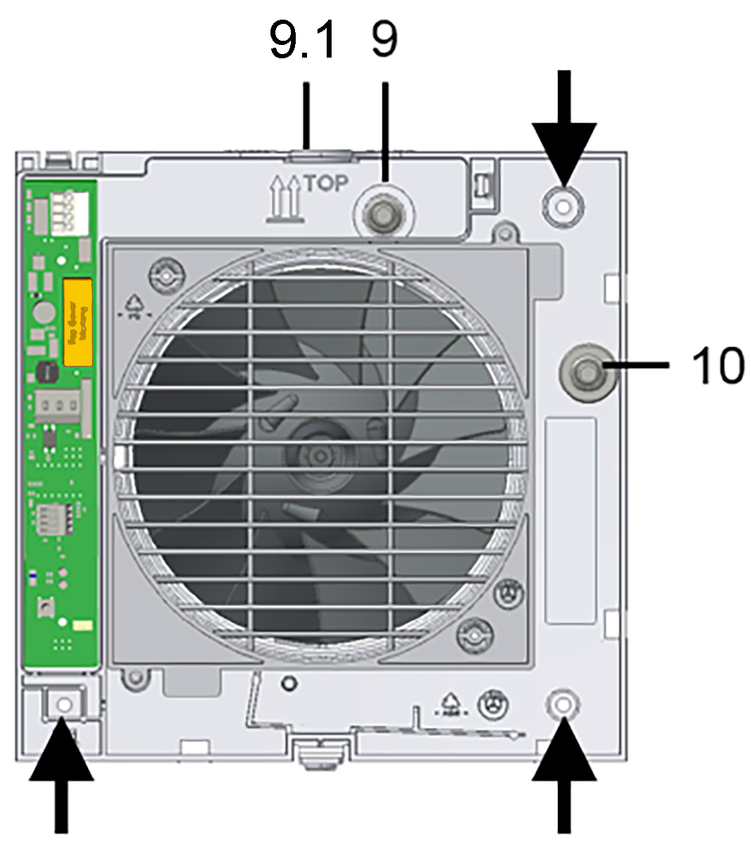
9
Cable grommet – flush-mounted connection
9.1
Housing segment – surface-mounted connection
10
Cable grommet – surface-mounted connection
- Align housing horizontally and mark both dowel holes, see arrow.
- Drill dowel holes with a Ø of 6 mm and insert dowels.
- Carefully push cable grommet (9) out of housing and remove it.
- For surface-mounted connection: Leave the upper cable grommet in the housing and remove the side cable grommet (10) from the housing.
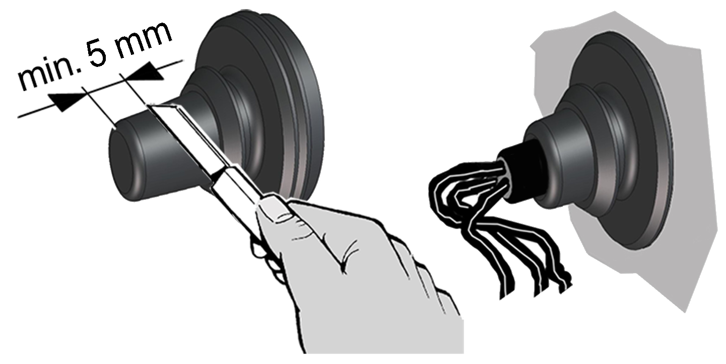
 Danger of short-circuits and damage to the unit. Water will penetrate if the power cable is incorrectly fed into the fan housing or if the cable grommet is not fitted correctly.
- Cut off cable grommet cap such that the cable grommet fits tightly round the power cable. Cut a minimum of 5 mm off the cap (power cable can bend better and electronics cover can be positioned correctly).
- Fit cable grommet correctly, seal on site if required.
- Insert cable grommet into housing.
- Feed power cable into the terminal compartment such that the cable grommet fits around the cable sheathing completely and does not penetrate too far into the terminal compartment.
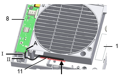
- Lead sensor connection cable, from the external combination sensor, into the opening (arrow) provided in the fan housing.
- Insert housing into wall breakthrough/wall sleeve and secure with two screws. Do not insert the housing such that it is twisted or crushed. Make sure you use mounting material which is sized for the purpose.
- Lay sensor connection cable in the provided recesses (I, II) and plug it [A] into the electronic circuit board.