Installation of spiral housing and upper part of housing
 Danger to life from electric shock.
- Prior to accessing the connection terminals, switch off all supply circuits. Switch off mains fuse, secure against being accidentally switched back on and position a visible warning sign.

- Press the desired number of sealing plugs out of the housing.
Centro-M with fixed air volume setting.
Centro-E and Centro-H with fixed air volume setting for basic ventilation. 
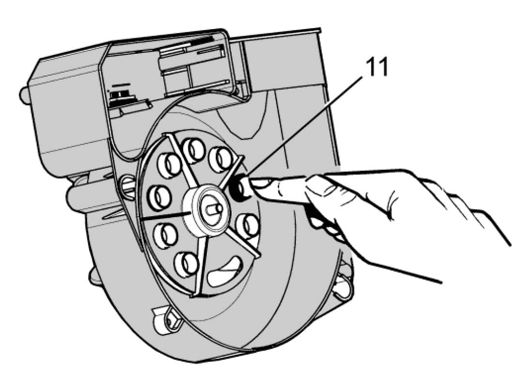
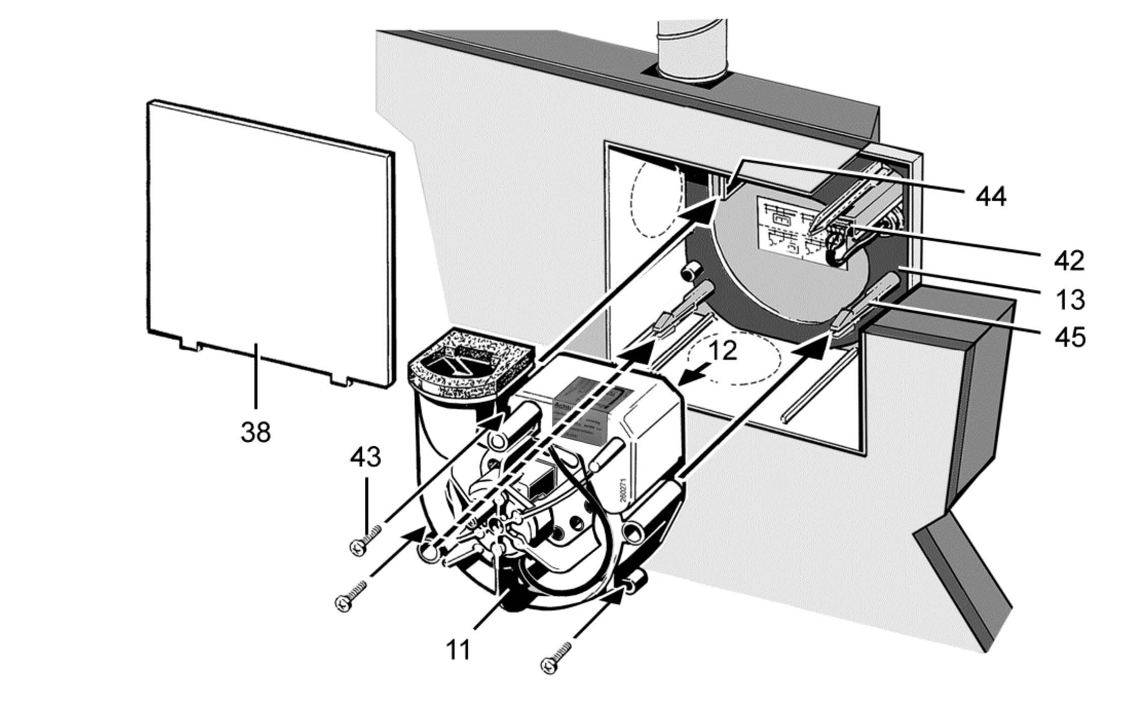
11
Spiral housing
12
Electronic circuit board (control)
13
Housing floor seal
38
Plaster protective cover
42
Connection terminal
43
Optional fixing with screws (to be provided by the customer)
44
Locking lever
45
Stud
- Switch off mains fuse and fit warning sign
- Remove plaster protective cover and clean any dirt off the flush-mounted housing.
- Ensure that the unit type ticked in the housing box matches the type to be fitted.
- Check ease of movement of shut-off shutter/backflow preventer.
When installed, the shut-off shutter/backflow preventer must close automatically. With ER-UPD and ER-UPB, this must close automatically due to the pressure of the inserted yoke spring (exception – upwards air outlet, see ER UP/Centro main instructions). With ER-UPD and ER-UPB ensure that the soldered strut is inserted correctly, see ER UP/Centro main instructions). - Check that the housing floor seal is correctly positioned, then insert properly.
 Risk of damage if ESD sensitive components on the board are touched.
Avoid direct touching of the components or contact surfaces.
 The sound level will increase if the housing floor seal is fitted incorrectly. Degree of protection not guaranteed if the housing floor seal is incorrectly positioned or missing.
The housing floor seal must lie flat and without any creases in the housing.
- Check that all screw connections are tight.
- Check ventilation ducts for dirt and clean if necessary.
- Check that connection data matches the technical data on the unit (rating plate).
 Function will be impaired if fan insert is not inserted correctly.
- Ensure proper insertion in the locking hooks.
- If the fan insert is not firmly seated, screw it to the housing at the 3 positions shown in the figure above. Suitable mounting material is to be provided by the customer.
Installation information in unit
 Function will be impaired if spiral housing is not inserted correctly.
- Ensure proper insertion in the 3 fixing points.
- Slide spiral housing evenly, in parallel, onto both studs. Ensure that the two locking tabs of the stud and the locking lever audibly engage so spiral housing is secure.
- Ensure that the spiral housing is correctly engaged. To do this, gently pull and press against the spiral housing. The spiral housing must not move in the process. Alternatively, screw the spiral housing tightly into the housing previous figure.