Electrically connecting the unit
- Switch off power supply circuits, position a visible sign warning against being accidentally switched back on.
- Open terminal box, route cables into terminal box and screw down with cable feedthrough. Cable screw connections according to standard EN 60079-1 (Ex “d”) must be used.
- The various types of cable entries (sleeves, cable screw connections or plugs) certified as described above must have the following thread:
| Motor | Cable entry, thread | Terminals | |||
n | ISO | NPT | ||||
3-phase | Mains connection | 56 – 71 | 1 | M20x1.5 | ½"-NPT | M4 |
1-phase | Secondary connection | 56 - 71 | 1 | M20x1.5 | ½"-NPT | M4 |
- An adapter can be supplied and fitted for deviating connections and other threads of the terminal box. The adapter must be certified according to EN 60079-0 and EN 60079-1 or EN 60079-7.
The table below shows the torques for the cable entries:
Metric | NPT | Permissible cable width range [mm] | Nm |
M12x1.5 |
| 2 - 5 | 7.5 |
M12x1.5 |
| 3 - 6.5 | 7.5 |
M16x1.5 | NPT 3/8" | 3 – 7 | 9 |
M16x1.5 | NPT 3/8" | 5 – 10 | 9 |
M20x1.5 | NPT 1/2" | 10 – 14 | 10 |
M20x1.5 | NPT 1/2" | 7 – 12 | 10 |
M25x1.5 | NPT 3/4" | 9 – 16 | 12 |
M25x1.5 | NPT 3/4" | 13 – 18 | 12 |
M32x1.5 | NPT 1" | 14 - 20 | 15 |
M32x1.5 | NPT 1" | 18 – 25 | 15 |
M40x1.5 | NPT 1 1/2" | 20 - 26 | 24 |
M40x1.5 | NPT 1 1/4" | 20 – 26 | 24 |
M40x1.5 | NPT 1 1/2" | 22 – 32 | 24 |
M40x1.5 | NPT 1 1/4" | 22 – 32 | 24 |
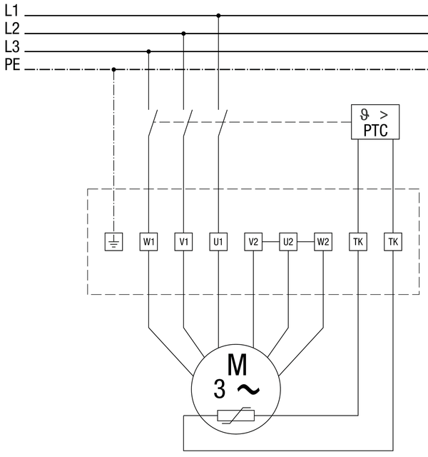
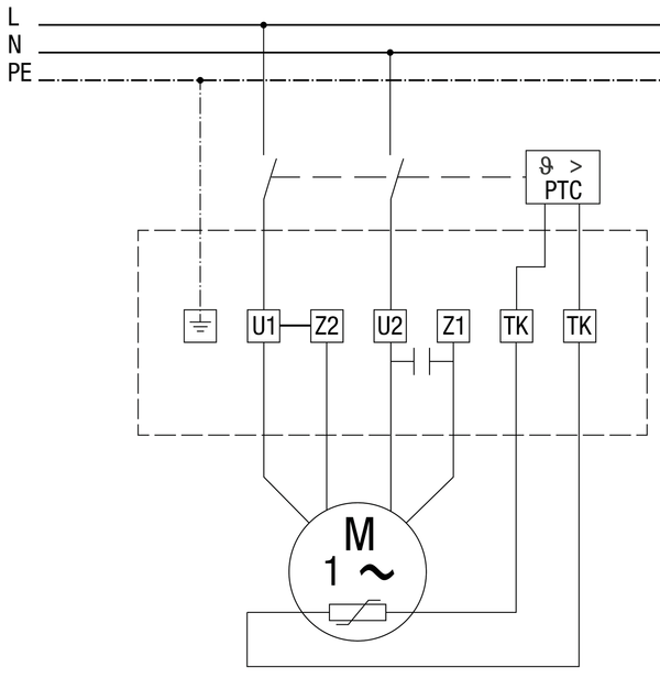
- Wire the unit electrically, install the PTC thermistor triggering system according to the relevant circuit diagram Circuit diagram. Every unused core line, in multi-core cables, must either be connected to earth at the end in potentially explosive atmospheres or be adequately insulated by terminals suitable for the type of ignition protection. Insulation with insulating tape alone is not permitted (EN 60079-14).
Fit terminal box cover for explosion protection. Ensure that there are no dirt particles in the terminal box and that the seal of the terminal box cover has close contact all the way around the terminal box. Please refer to the following table for tightening torques.
Thread | M4 | M5 | M6 | M8 | M10 |
Tightening torque [Nm] | 2 | 3.2 | 5 | 12 | 18 |
- If necessary, fit an on/off switch (provided by the customer).