Connect the fan electrically
 Note: Risk of damage to unit in the event of short-circuits. Insulate any cable cores that are not needed.
Note prescribed tightening torques.
Components | Tightening torque |
|---|---|
Terminal box cover: M4 stainless steel cylinder head bolts | 1.0 Nm |
Sheath terminal M7 x 0.75 mm | 0.7 Nm |
Motor terminals TK | 0.7 Nm |
- De-energise the system.
- Remove the two ring nuts and two lock nuts from the weather protection hood and take off the hood.
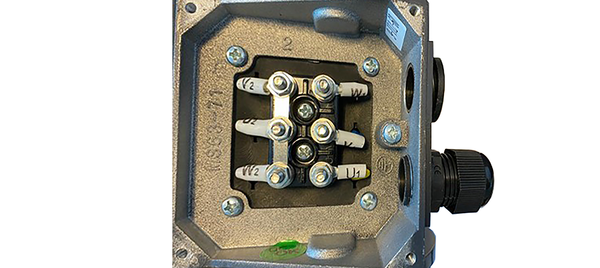
- Remove the terminal box cover.
- Guide power cable from below at fan along to terminal box (across one corner of the motor plate). Ensure that the weather protection hood can be fitted correctly; the cables must not be damaged.
- Attach the required cable screw connections and blind plugs (provided by the customer) to the terminal box, guide the power cable through the cable screw connection into the terminal box and secure it with the tension relief.
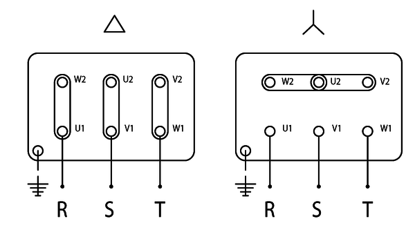
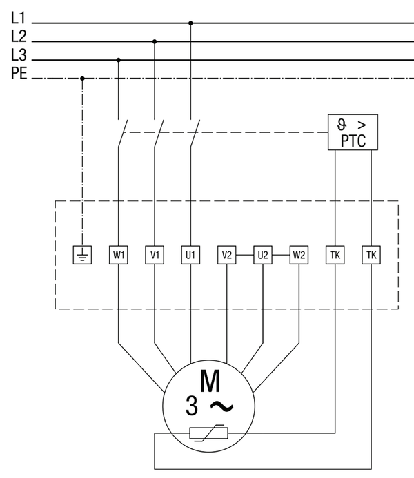
- Wire the fan to the electrics according to the circuit diagram → sticker in terminal box or corresponding wiring diagram in the appendix. Tightening torque of terminals 1 Nm. Ensure PE conductor connection.
- Install appropriate overload protection (PTC thermistor triggering system ) → Overload protection chapter and Maico’s range of accessories at www.maico-ventilatoren.com.
- Put the terminal box cover on and screw it into place. NOTICE: Risk of short-circuits if terminal box not watertight. Ensure correct line feedthrough and cable screw connections/blind plugs.
- Place weather protection hood on fan housing and screw down with the two ring nuts and two lock nuts (tightening torque 10 Nm). Ensure that the fan’s protective grille is correctly installed too.
- Switch the mains fuse on.
- Move inspection switch into position (1/On).