Final mounting
 due to short circuit/fire if moisture penetrates into the terminal compartment. A flat installation position is prescribed for the electronics cover, not curved! This must lie tightly against the housing all around.

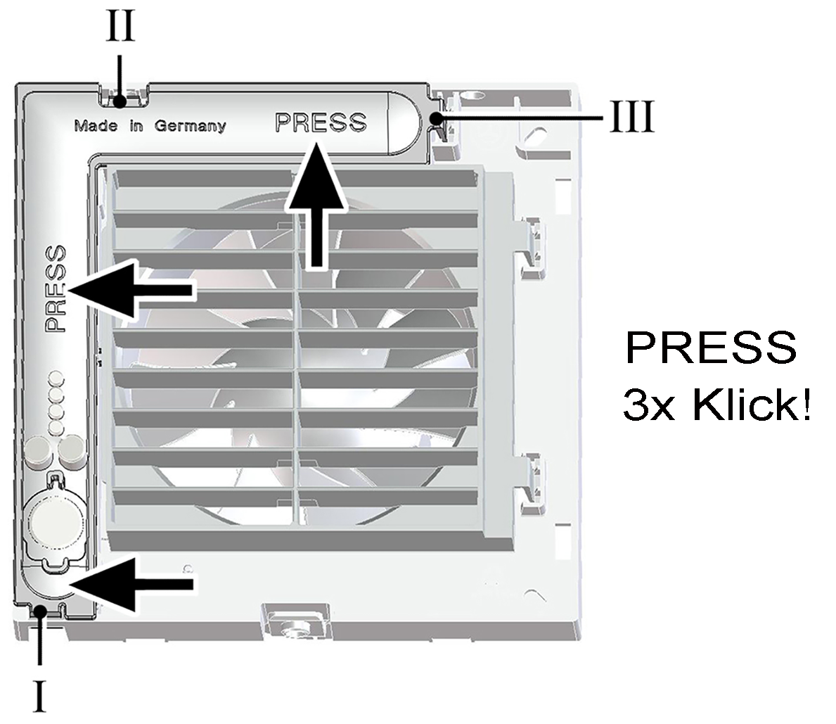
I, II, III | Locking tabs |
- Push the electronics cover onto the 3 locking tabs at the housing recesses I, II and III, one after the other, until it clicks into place. Press the electronics cover firmly into the housing at both positions indicated by the word PRESS. Ensure tightness to the housing.

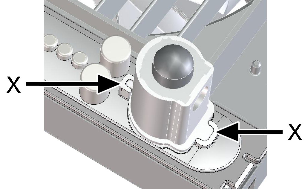
- For device versions F, KF, H, KH, B and KB, insert the supplied sensor in the correct position (→ arrows X), into the connector socket.
and KH: Do not touch/push on the membrane on the flat side of the sensor wall, otherwise it will be damaged.

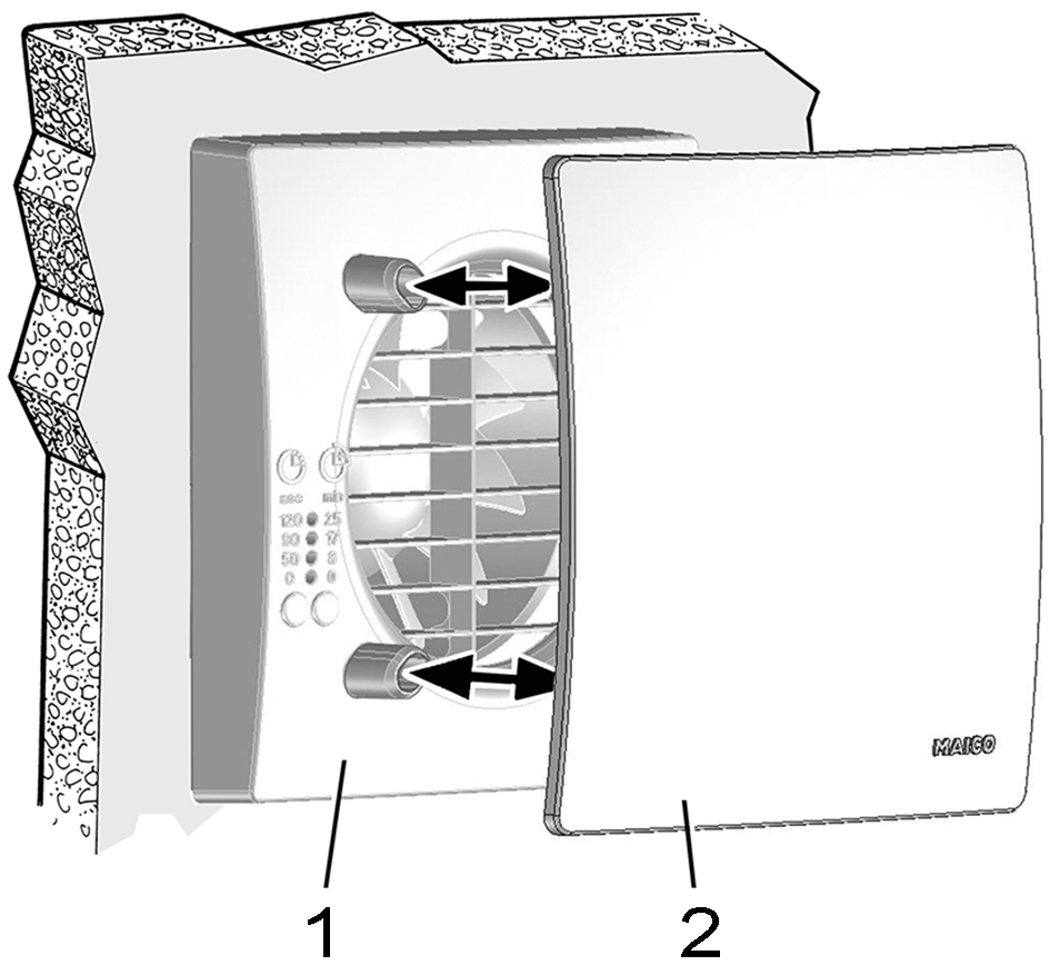
1 | Housing cover |
2 | Design cover |
- Attach housing cover.

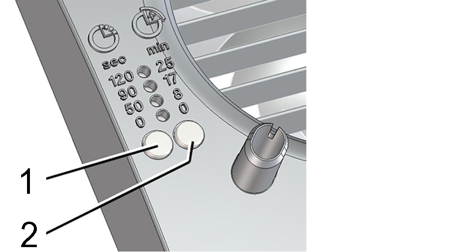
1 | Setting button for start delay |
2 | Setting button for overrun time |
- Use the setting keys to set the start delay and overrun time.
Press the setting key once, the current setting is displayed.
Press the setting key repeatedly until the desired LED for the start delay time lights up.
Wait until the LED flashes twice and goes out. The value is now saved. - Fit design cover.
- Activation after next switch-on.
- No start delay for the ECA 100 ipro, ECA 100 ipro K, ECA 100 ipro B and ECA 100 ipro KB variants. No overrun time for the ECA 100 ipro and ECA 100 ipro K variants.
- Factory setting – start delay of 50 seconds. Variants F and KF = 0 seconds. Factory setting – overrun time = 8 minutes.
 H
H