Electrical connection
 Danger to life from electric shock.
- Prior to accessing the connection terminals, switch off all supply circuits. Switch off mains fuse, secure against being accidentally switched back on and position a visible warning sign.
 Danger from electric shock/The unit will be damaged if installed incorrectly with too long a power cable.
If the cable feed is too long inside the housing, the fan insert cannot be installed correctly. The power cable may be damaged when inserting the fan unit.
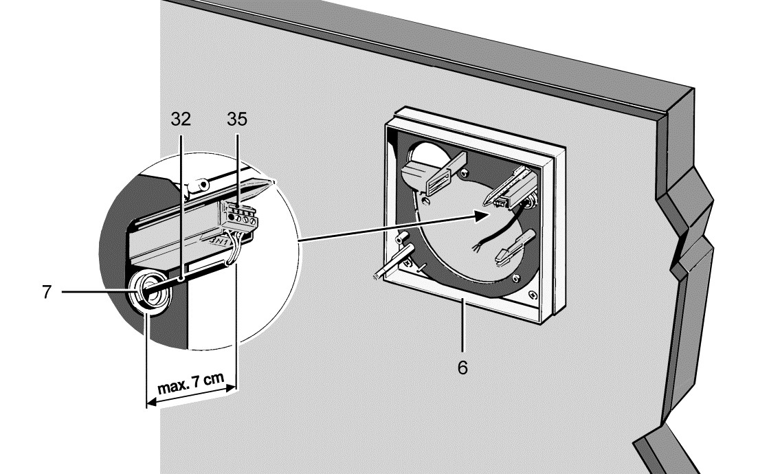
- Area for mains connection labelled: Lay wires according to the contour. Note that the maximum spacing to the connection terminal box is 7 cm. Do not cut the power cable inside the housing too short.
 Risk of damage if ESD sensitive components on the board are touched.
Avoid direct touching of the components or contact surfaces.
 Damage to the unit if connected incorrectly.
For example, if an electric load is connected to terminal 4 or if connected to 2 phases.
- Connect the unit according to the wiring diagrams: Wiring diagrams. Do not connect additional consumers to terminal 4.
 Damage to unit due to removal of the humidifying membrane.
If the humidifying membrane on the sensor dome is removed, the degree of protection is no longer guaranteed.
 Risk of damage to unit in the event of short-circuits.
- Cut off and insulate PE conductor and individual cable cores that are not required!
Always note the relevant specifications for electrical installations and when fitting equipment. In Germany, observe DIN VDE 0100 and the corresponding parts in particular. In rooms with baths or shower units, for example, this would be Part 701.
- Switch off mains fuse, secure and fit warning sign.
- Remove power cable’s sheathing and cut to length as described.
- Cut off and insulate PE conductor and individual cable cores that are not required.
- Make electrical connection according to circuit diagram on terminal box: Wiring diagrams.

 To prevent the unit and/or electric components from malfunctioning as a result of reverse polarity voltages and induction (incorrect ignition or glowing/flaring of LED, energy-saving or neon lamps), the unit and electric components connected in parallel, such as room lighting, should be connected via a double-pole switch.