Wall and ceiling installation, electrical connection
|
|
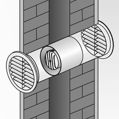
NOTICE: Install ERV only in combination with a WH 120 / WH 150 wall sleeve. Damage to unit/functional problems in the event of rubbing impeller.
Do not insert the housing such that it is twisted or crushed.
NOTICE: Risk of short circuits/damage to unit if condensation builds up in the fan housing. Thermally insulate ventilation ducts properly.
 Cut off and insulate PE conductor and individual cable cores that are not required. Guide power cable correctly through cable grommet into unit to avoid damage (e.g. from condensation). The cable grommet must tightly seal the connection cable.
- Fig. B: Remove the terminal compartment cover. Attach the cable grommet.
- Fig. C, pos. I: If desired, break out the recess at the predetermined knockout point of the side wall of the fan (9:00 o'clock position) in order to lead the cable from outside the fan to the terminal compartment.
- Attach the two Tesamoll strips supplied.
- Align the housing and slide it into the wall sleeve. Install the unit so that the rating plate is at the bottom at 6:00 o’clock position → position marking on rating plate.
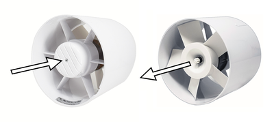
Fig. on left = air extraction installation position
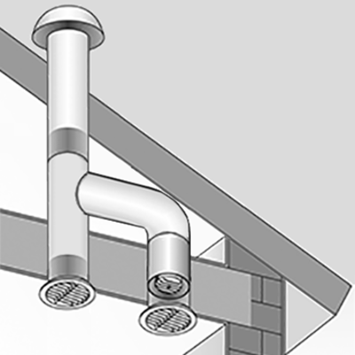
Fig. on right = ventilation installation position - Fig. D: In the case of ceiling installation, secure the fan against falling with 3 screws. Suitable mounting material is to be provided by the customer.
- Fig. E: Guide the power cable through the cable grommet and connect it according to the circuit diagram. Fit tension relief.
- Fig. F: Set the overrun time for ERV 120 TC and ERV 150 TC (3...25 minutes).
- Fig. G: Check the final position of the housing. Check correct installation position → position marking (rating plate at 6:00 o’clock position). Observe cable routing in the wall sleeve.
- Screw the terminal compartment cover to the housing.
- Protect the core drill hole with protection against accidental contact. Attach external grille SG 120 or SG 150/1.