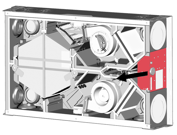
Installation of optional additional components
 Notice: Make sure that the connected electrical cables are not jammed or crushed. Do not load the spring-type terminals on the electronic circuit board.
- Removing the front cover→ Removal/installation of the front cover.
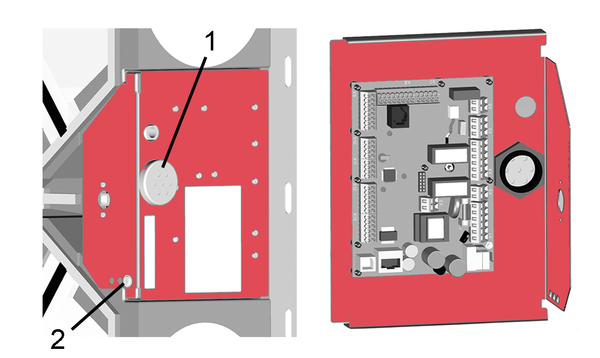
1 | 7-way cable feedthrough |
2 | Retaining screw for electronics slide-in module |
- Remove the retaining screw of the electronics slide-in module and pull the electronics slide-in module (with main board) out of the ventilation unit.
- Connect the additional component on the main board according to the wiring diagram. For retrofitting and connecting a VOC or CO2 sensor → Retrofitting VOC/CO2 sensor. For connection of additional components → Installation instructions of the accessories.
- Guide the connection cable of the control unit(s) and additional components through the 7-way cable feedthrough into the ventilation unit. Ensure seal integrity (IP protection).
- Slide the electronics slide-in module into the two guide rails of the ventilation unit and screw it in place with the retaining screw.
- Attaching front cover→ Removal/installation of the front cover.
- Mount the control unit(s) and external additional components at the installation site and wire them electrically according to the wiring diagram (appendix).
- Switch the mains fuse on. On the RLS 1 WR control unit, the LEDs switch on; the start screen appears on an optional RLS T2 WS control unit.
- Carry out a function test and put the ventilation unit into operation → Commissioning.