External sensors
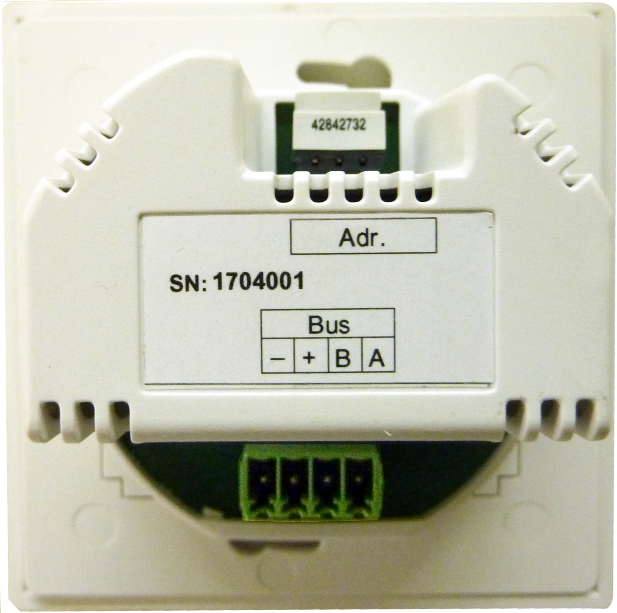
The connection of a wired external sensor, takes place on the RS 485 interface of the RLS 45 O / RLS 45 K control (max. 3 sensors per control).
Demand-driven operation (sensor-controlled automatic operation) only applies to ventilation units, which are connected to the same room air control as the sensors.
External sensors which can be connected
- PP 45 HY humidity sensor module
- PP 45 CO2 CO2 sensor module
- PP 45 VOC VOC sensor module
Connecting sensors
- Install and wire external sensor → Installation instructions for final installation kit.
- With external sensors, addressing is undertaken using the rotary switch on the sensor housing:
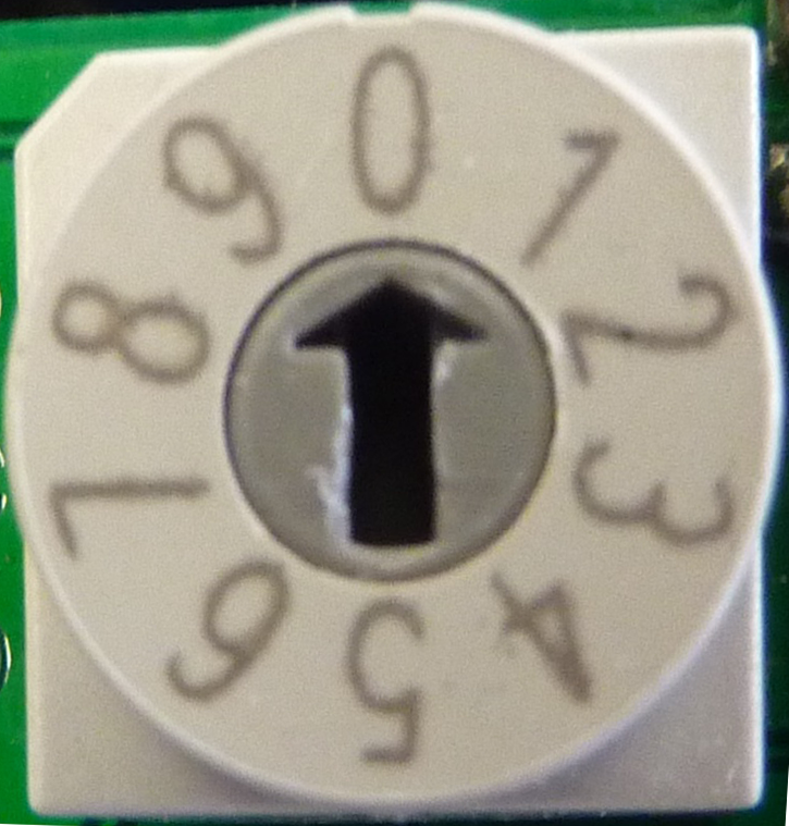
Position 0 = sensor 1, position 1 = sensor 2, position 2 = sensor 3
The sensors (external and internal) are only taught-in on the master.
- Take room air control out of flush-mounted box and wire sensor connection cable to plug-in connection terminal of RS 485 interface → Wiring diagrams in installation instructions for final installation kit.
- Insert room air control in the flush-mounted box and screw down to flush-mounted box with 2 screws.
- Fit front panel. Make sure it locks into position. With front covers, ensure that sensor opening (hole in front panel) is above the sensor.
- Commissioning ventilation system→ Commissioning.
- Activating sensor: In service mode → Installation instructions for final installation kit or with the (Commissioning software.