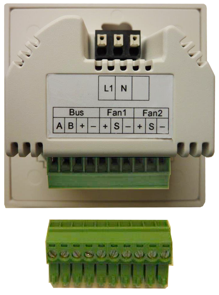
Connecting RLS 45 K

RLS 45 K room air control is used to activate PPB 30 O / PPB 30 K units.
- Take off frame of room air control.
- Connect thePPB 30 O to the RLS 45 terminals FAN1 and FAN 2. Connect PPB 30 K units to RS 485 bus.
- The power supply to the PPB 30 K (+) MUST come from the Fan1 or Fan2 connection. Make connection according to wiring diagram → Connection and wiring diagrams.
- A combination of PPB30 O and PP 45 units is not permitted at the FAN1 and FAN2 connection terminals of the RLS control.
- No exhaust air function is possible for PPB 30 O units on an RLS 45 K control.
- If a PPB 30 K is running in exhaust air mode, the PP 45 / PPB 30 O units handle the volumetric flow compensation at the fan interface (Fan1/Fan2). It is important that the unit type + quantity are set correctly.
- Insert room air control in the flush-mounted box and screw down to flush-mounted box with 2 screws.
- Fit frame. Ensure that the sensor opening is above the PP 45 HYI (if fitted) and that the frame engages.
- Commissioning ventilation system→ .
 Information