Connection diagram for RLS 45 O – System bus
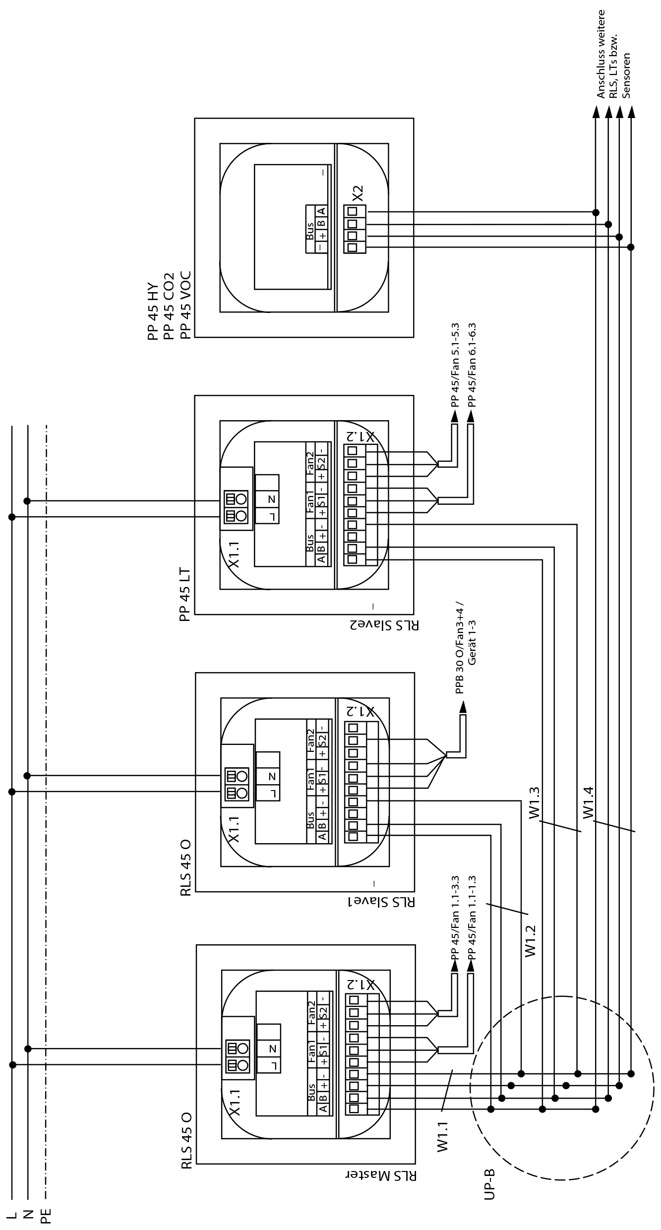
RLS 45 O | PP 45 O room air control |
PP 45 LT | PP 45 power unit |
PP 45 HY | PP 45 humidity sensor for flush mounting |
PP 45 CO2 | PP 45 CO2 sensor for flush mounting |
PP 45 VOC | PP 45 VOC sensor for flush mounting |
X1.1 | Mains connection terminal |
X1.2 | Fan/bus connector bush |
X2 | RS-485 bus connector bush |
Fan 1.1-1.3 | Ventilation unit 1, 3, 5 on RLS Master |
Fan 2.1-2.3 | Ventilation unit 2, 4, 6 on RLS Master |
Fan 3.1-3.3 | Ventilation unit 7, 9, 11 on RLS slave 1 |
Fan 4.1-4.3 | Ventilation unit 8, 10, 12 on RLS slave 2 |
Fan 5.1-5.3 | Ventilation unit 13, 15, 17 on RLS slave 2 |
Fan 6.1-6.3 | Ventilation unit 14, 16, 18 on RLS slave 2 |
UP-B | Flush-mounted distributor bus, connection of RLS,LT, EO module and sensors using RS-485 bus interface |
W1.X | Bus connecting cable (RS-485). Recommended control cable J-Y (ST) Y 2x2x0.8 mm. |