Connection diagram for RLS 45 K - PPB 30 K
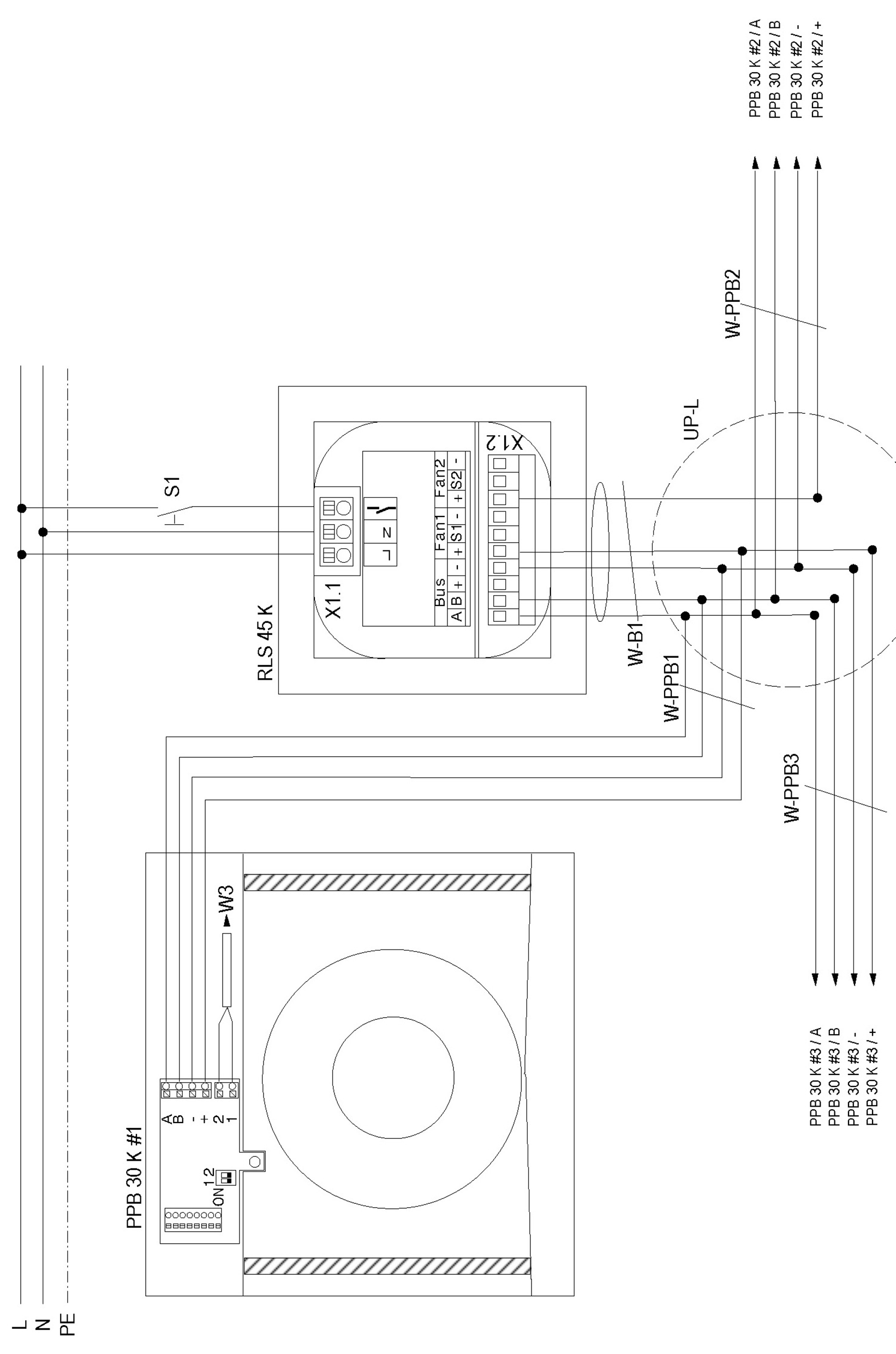
The power supply to the PPB 30 K (+) MUST come from the Fan1 or Fan2 connection. For addressing → Unit connection.
RLS 45 K | PushPull 45 Comfort room air control |
PPB 30 K #1 | 1 PushPull Balanced 30 Comfort ventilation unit |
PPB 30 K #2 | 2 PushPull Balanced 30 Comfort ventilation unit |
PPB 30 K #3 | 3 PushPull Balanced 30 Comfort ventilation unit |
S1 | Button/switch for additional function (sleep mode, intensive mode, supply air mode, safety function) |
UP-L | Flush-mounted distributor for connection of ventilation units. Connection of all ventilation units in a star configuration to the distributor. |
W-B1 | Control line bus PPB: Recommended control cable J-Y(ST)Y 2x2x0.8 mm. Max. length to distributor 4m. |
W-PPBX | PPB 30 control cable (bus), recommended control cable J-Y(ST)Y 2x2x0.8mm. Max. cable length from UP-L distributor to PPB 30 K ventilation unit = 25 m. |