Connection diagram for RLS 45 O– PPB 30 O:
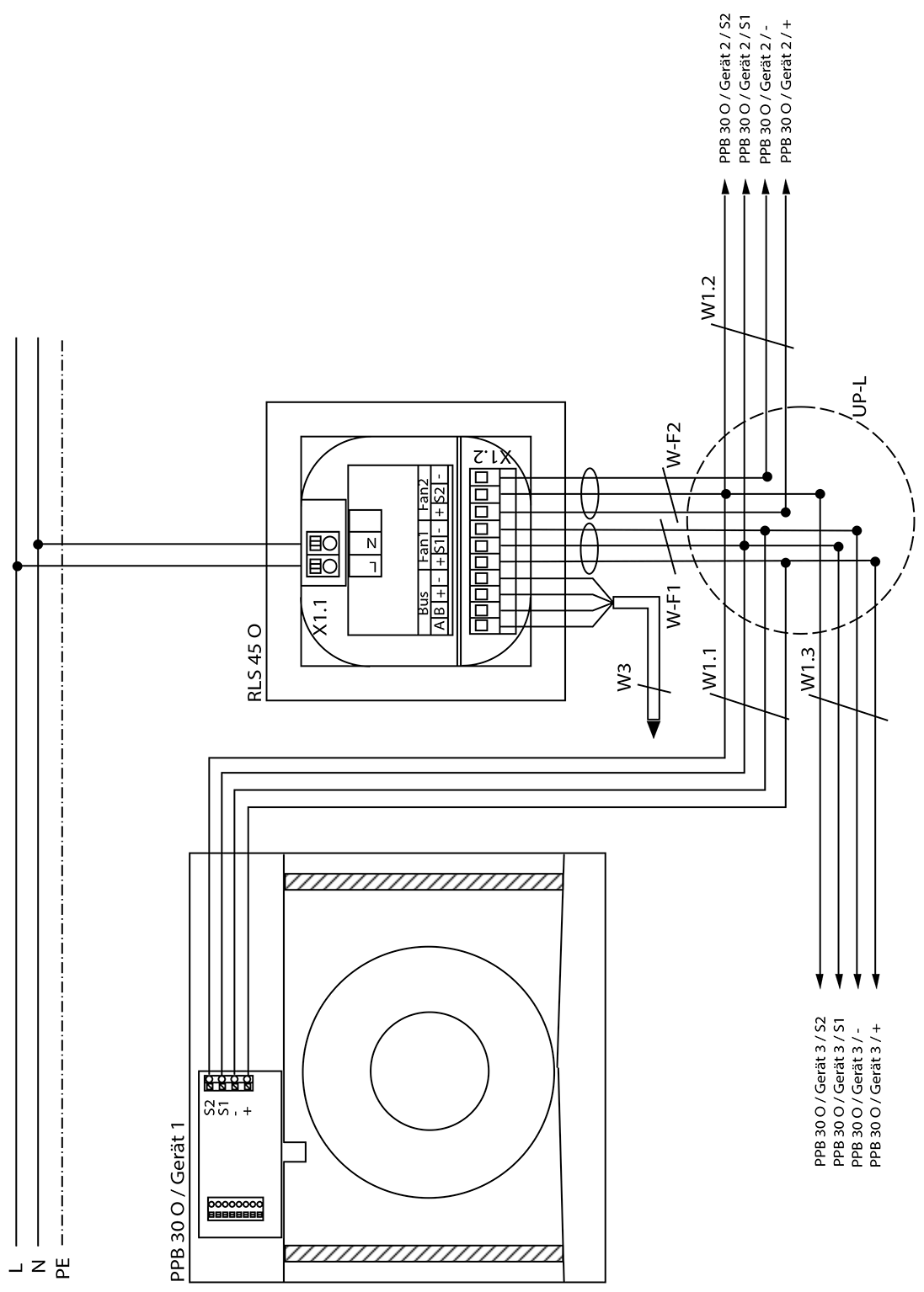
RLS 45 O | PushPull 45 Object room air control |
PPB 30 O | PushPull Balance 30 Object ventilation unit |
X 1.1 | RLS – mains connection terminal |
X 1.2 | RLS – Fan/bus connection terminal |
UP-L | Flush-mounted distributor for fan units, connection of all fan units in star shape to distributor |
W-F1: Fan 1 | Control line for Fan 1/Fan 2: Recommended control cable J-Y (ST) Y 2x2x0.8 mm. Max. length to distributor 4m. |
W1.X | Fan unit control cable. Recommended control cable J-Y (ST) Y 2x2x0.8 mm. Max. cable length from UP-L distributor to PP 45 ventilation unit = 25 m. |
W3 | Bus connecting cable (RS-485). Recommended control cable |