6) Building control system
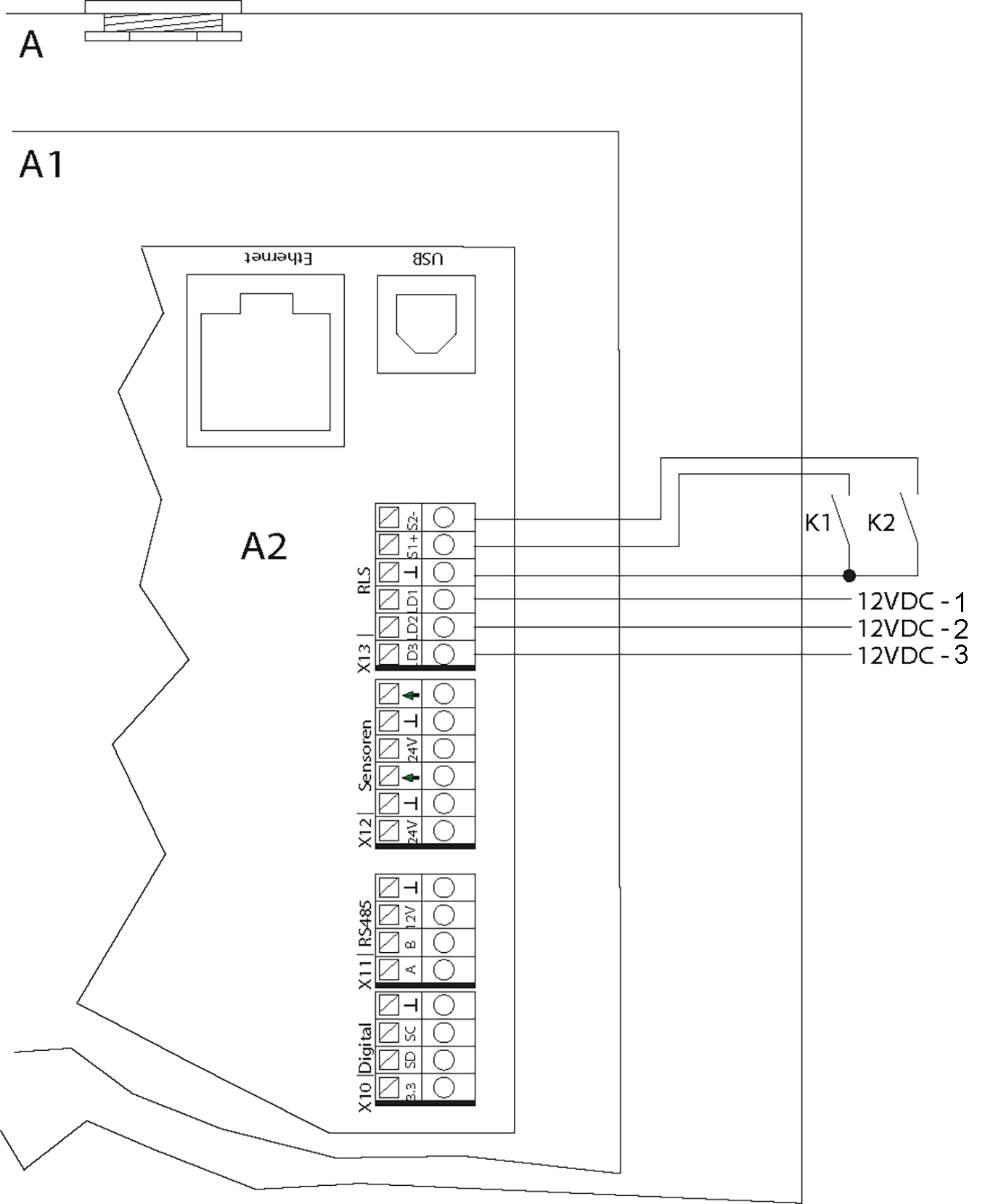
Wiring diagram of Integration in building control system
A | Ventilation unit |
A1 | Electronics slide-in module |
A2 | Controlled domestic ventilation unit control |
12VDC-1 | Operating display |
12VDC-2 | Filter change indicator |
12VDC-3 | Fault message |
Ventilation level | K1 | K2 |
|---|---|---|
Off* | Off | Off |
RV | On | Off |
NV | Off | On |
IV | On | On |
* With the setting “Ventilation level off blocked”, the unit runs in humidity protection ventilation level
If the RLS 1 WR single control unit setting is changed to digital, the controlled domestic ventilation unit can be controlled using a switching actuator (e.g. KNX). This allows the controlled domestic ventilation unit to be integrated in a building control system. The actuator’s potential-free contacts must be configured for switching 12 VDC.