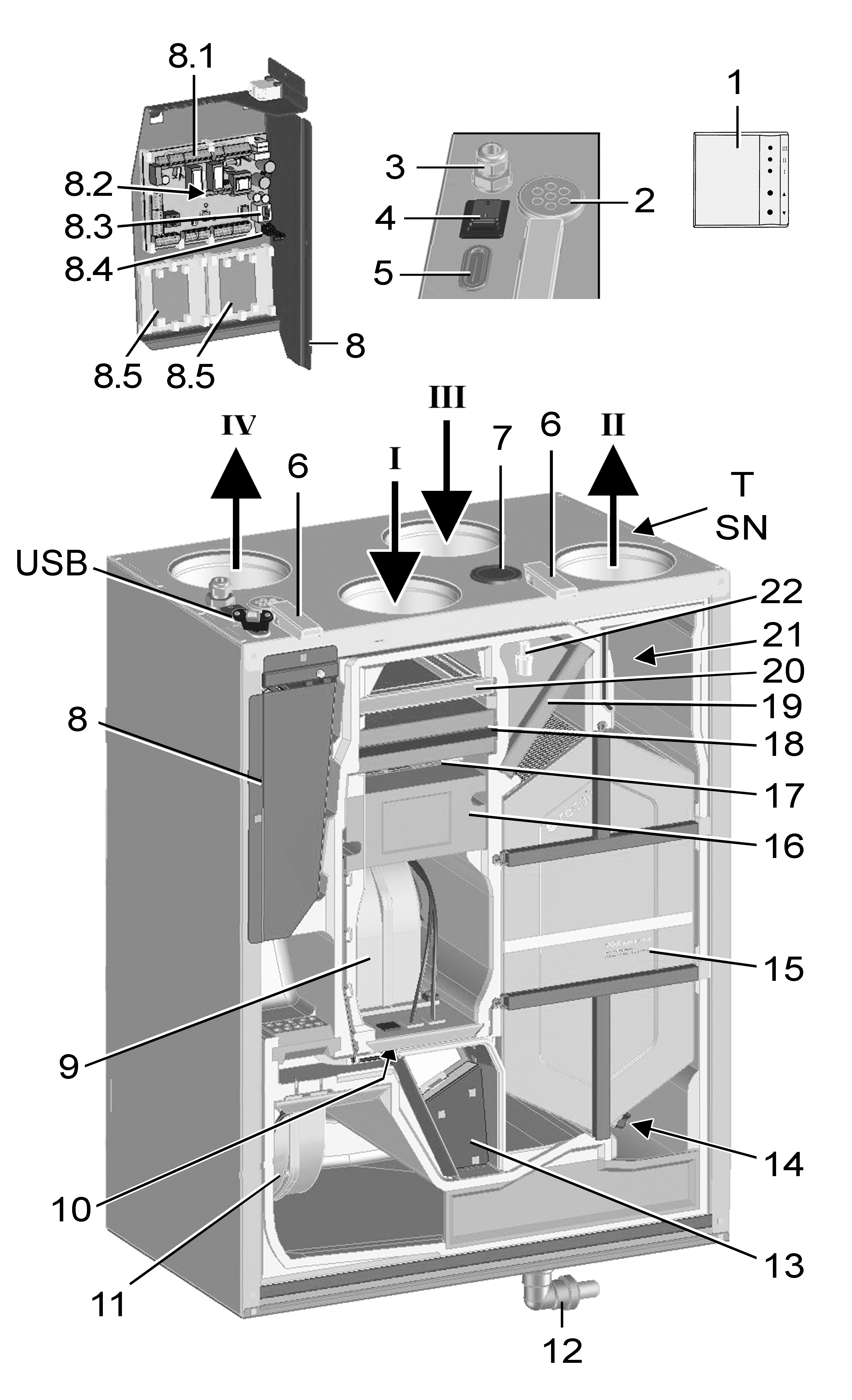
Structure / duct connections

Fig.: WS 170 KBR/KBRET in right-hand version.
WS 170 KBL/KBLET in left-hand version, mirror image.
I | Outside air |
II | Supply air |
III | Exhaust air |
IV | Outgoing air |
1 | RLS 1 WR single control unit. Alternative control units: RLS T1 WS, RLS T2 WS or RLS G1 WS. |
2 | Cable feedthrough – power cable |
3 | Cable feedthrough – USB, Ethernet |
4 | Main switch |
5 | Membrane grommet with slot |
6 | Quick-release clip |
7 | Seal plug |
8 | Electronic slide-in module with: |
8.1 | Main board A1 |
8.2 | Interface for KNX or EnOcean plug-in module |
8.3 | Ethernet interface |
8.4 | USB port |
8.5 | Additional board ZP 1 and/or ZP 2 (both optional). Combination can be selected freely. |
9 | Outside air/supply air fan |
10 | Outside air temperature sensor |
11 | Exhaust air/outgoing air fan |
12 | Condensate elbow with reducer |
13 | Bypass module |
14 | Outgoing air temperature sensor |
15 | Cross-counterflow heat exchanger, optional enthalpy heat exchanger |
16 | Preheating register |
17 | Protective grille for preheating register |
18 | Pollen filter, filter class F7 |
19 | Air filter, filter class G4 |
20 | Air filter, filter class G4 |
21 | Supply air temperature sensor |
22 | Combi sensor: Exhaust air humidity / exhaust air temperature |
T | Rating plate |
SN | Serial number |
USB | USB connection on the outside |