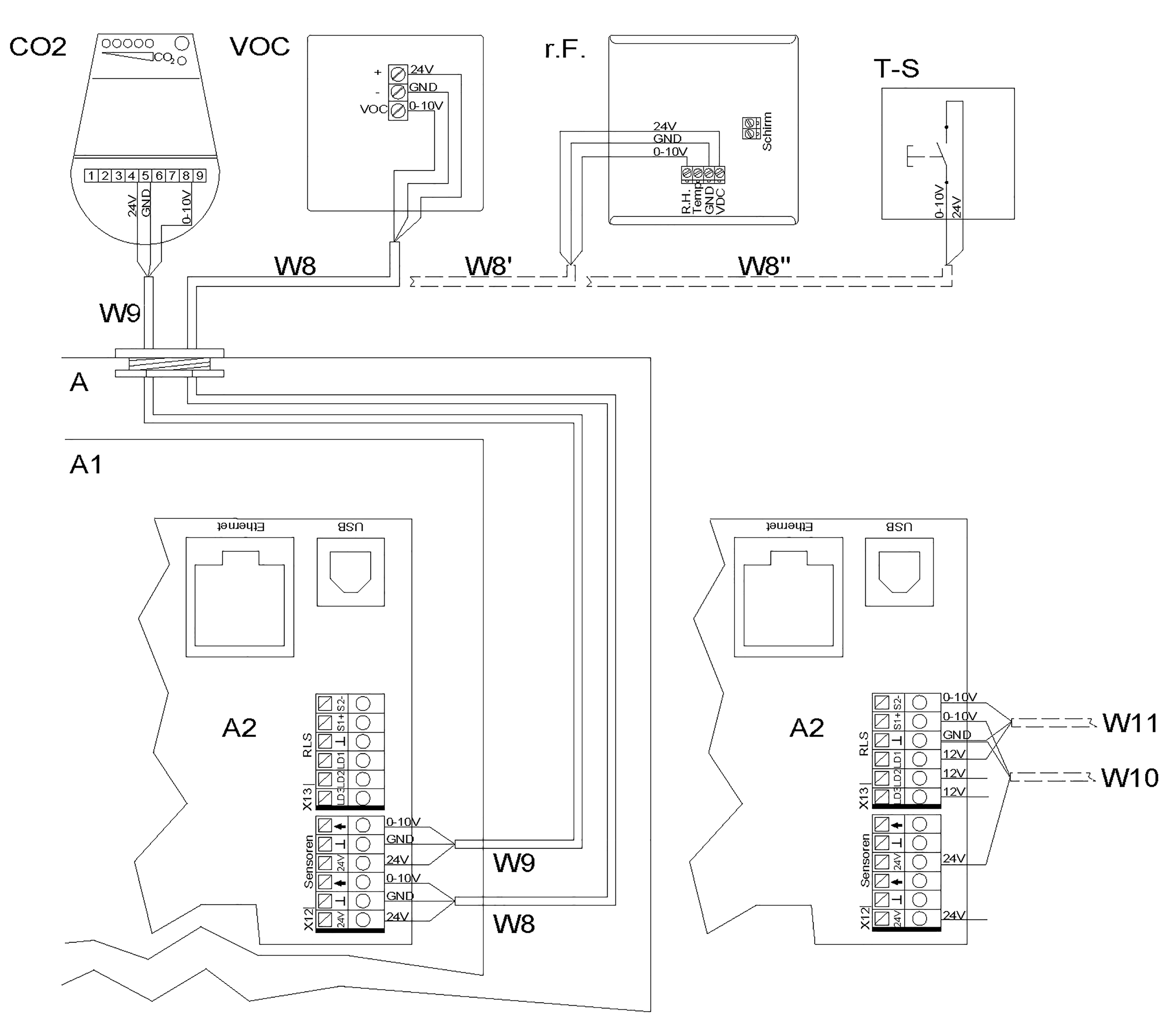
2) WR 310/410, WS 320/470

External sensors wiring diagram
A | Ventilation unit |
A1 | Electronics slide-in module |
A2 | Controlled domestic ventilation control |
CO2 | CO2 sensor (accessories) |
VOC | Air quality controller (accessories) |
r.h. | Humidity sensor (accessories) |
T-S | Intermittent ventilation button / external potential-free contact |
W8 | Connection cable (provided by customer) for external VOC sensor, e.g. LIYY 3 x 0.5 mm² |
W8’ | Connection cable (provided by customer) for external r. h. sensor 1, e.g. LIYY 3 x 0.5 mm² |
W8’’ | Connection cable (provided by customer) external pushbutton / potential-free contact (function – intermittent ventilation/sensor type = digital), |
W9 | Connection cable (provided by customer) for external CO2 sensor 2, e.g. LIYY 3 x 0.5 mm² |
W10 | Connection cable (provided by customer) for external sensor 3, e.g. LIYY 3 x 0.5 mm² |
W11 | Connection cable (provided by customer) for external sensor 4, e.g. LIYY 3 x 0.5 mm² |
The control’s sensor inputs can be freely parametrised. The inputs are not defined for a particular sensor type.
When commissioning a sensor, the sensor input on the control must be activated and the sensor type specified → Sensor settings. If the RLS 1 WR is deactivated on the control unit (parameter single control unit inactive), up to 4 sensors can be connected. The power supply to sensors 3 and 4 can be ensured via terminals LD1, LD2, LD3 (all 12 V DC) or with double assignment, via the 24 V DC supply of sensor connections.