Retrofitting PTC heat register
- Powerbox H: Remove WS 75 APA/UPA/UPGA cover. Powerbox S: Remove any cover that may be present.
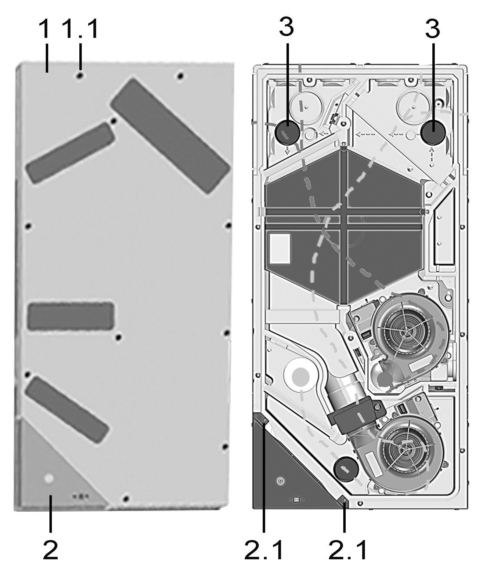
1
Housing cover
1.1
Screws for housing cover, 10 pieces
2
Electronics compartment with main circuit board A1
2.1
Fastening screws for electronics compartment
3
EPP sealing plugs
- Remove the cover of electronics compartment (2 screws).
- Remove both of the upper EPP sealing plugs.
 Guide the connecting cable, in 3 steps, into the electronics compartment. For this, use a pulling aid (wire/wire cable), otherwise the installation is difficult due to 90° bends. Ensure tight cable routing. For cable routing → Figure.
- Pierce EPP housing, with screwdriver, at the round marking, pos. ①.
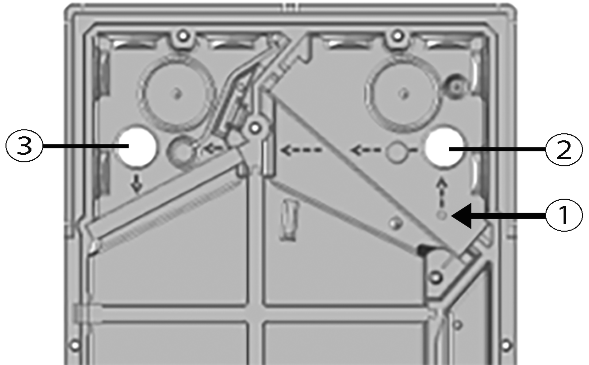
- Thread cable through hole at pos. ① to pos. ②. Observe arrows in EPP housing.
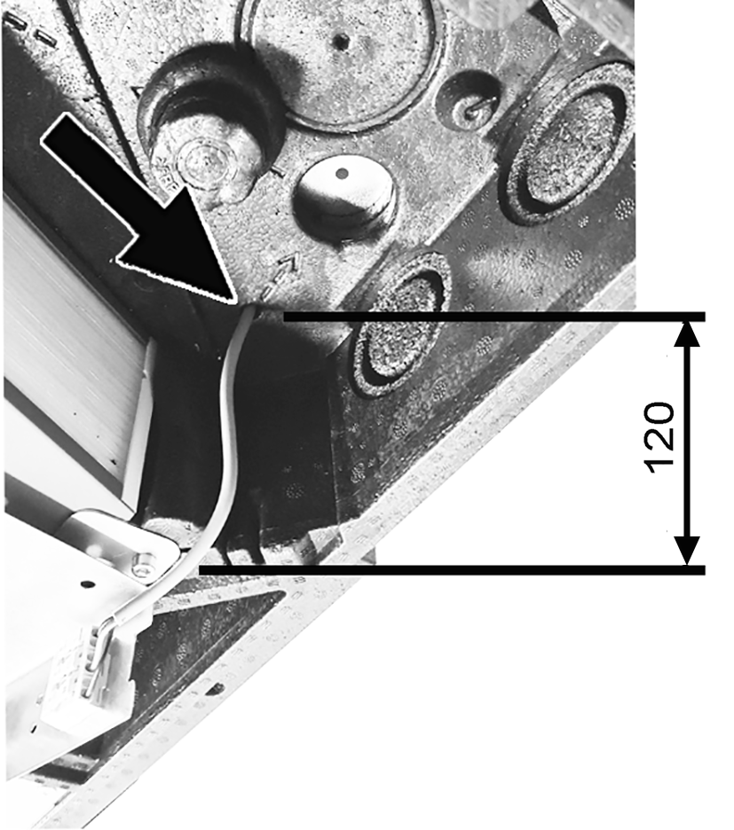
Maintain the distance between the edge of WS 75 NH board and the EPP hole=120 mm.
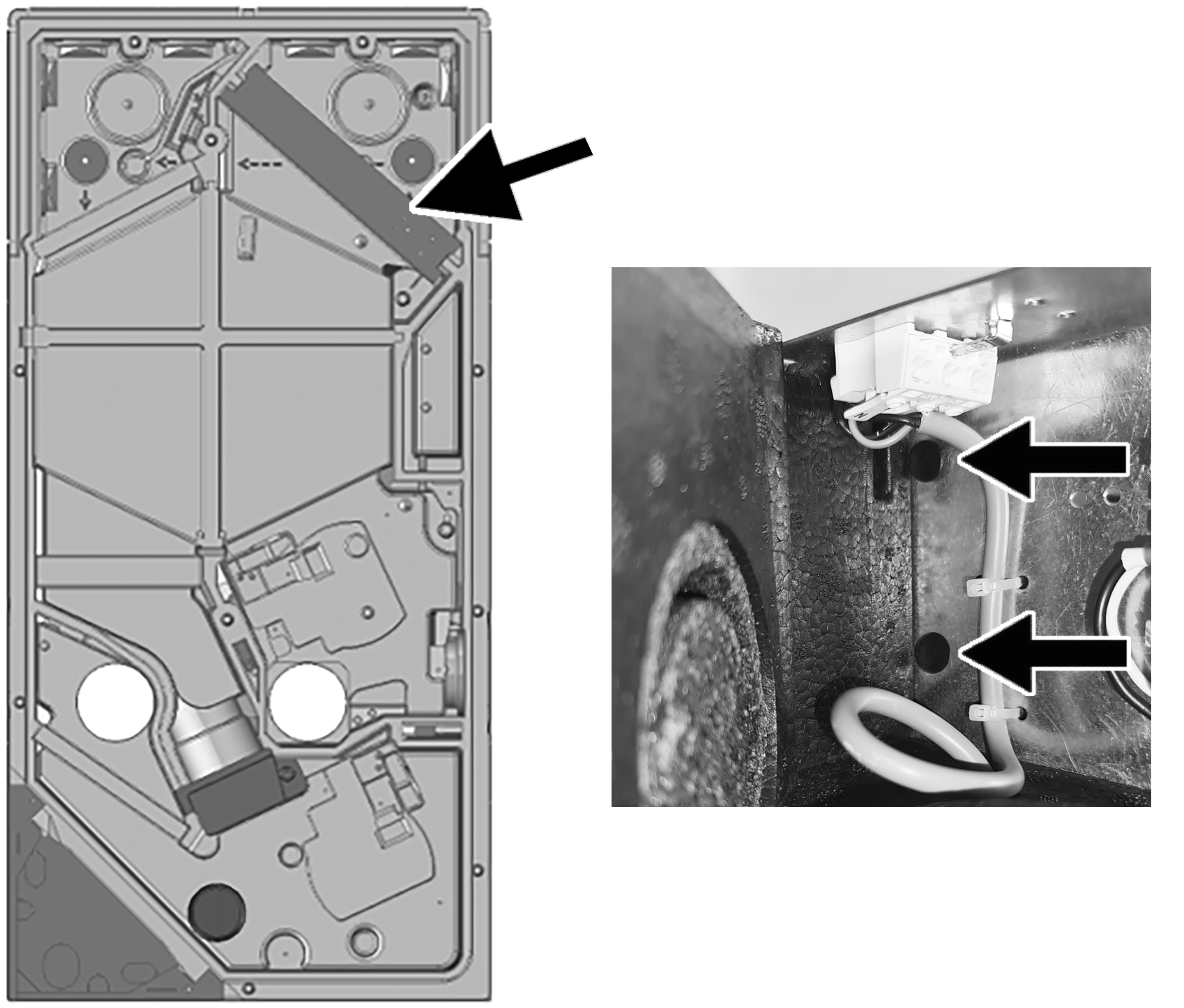
- Insert the PTC heat register module into the two slots in the EPP housing and secure it with the two plastic locking pins (arrows) provided.
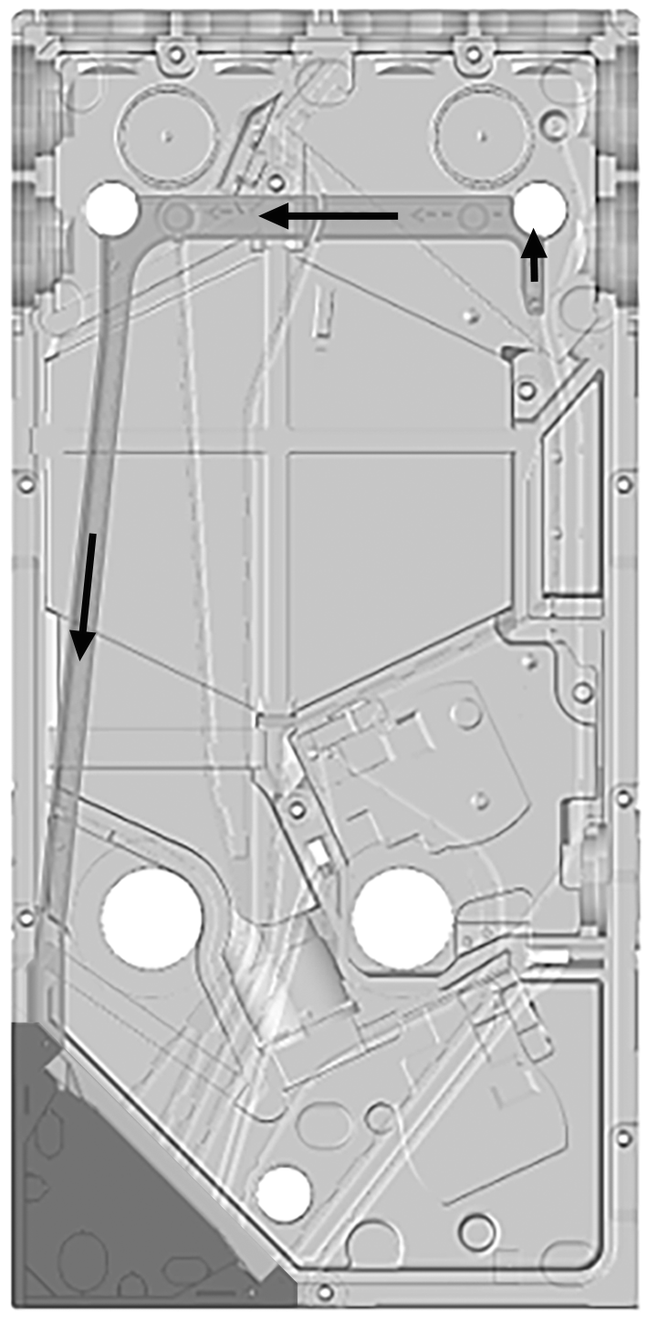
- Make a 90° elbow in the connecting cable and thread the cable from pos. ② to pos. ③. Observe arrows in EPP housing.
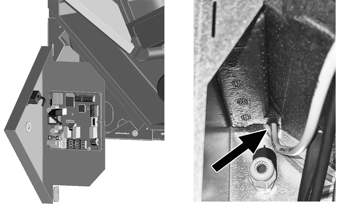
- Make a 90° elbow in the connecting cable and thread the cable from pos. ③ into the electronics compartment. Observe arrows in EPP housing.
- Connect the connection cables to the spring terminal X5 of the main circuit board → Wiring diagram.
- Insert both EPP sealing plugs into the EPP housing.
- Install the cover, electronics compartment and front cover.
- Attach housing cover.
- Perform function test via the switching test function
 . Using the commissioning software, set the Supply air heat register parameter to on in the main menu Settings/Switching test. After a short time the supply air fan starts. When functioning correctly, heated air flows out of the supply air opening. Set Supply air heat register parameter to off.