Feed in connection cables, install shell tray
- Push the power cable from the rear through the cable feedthrough. If the control unit is placed externally (outside the UPA/UPGA cover), also insert the control cable through cable feedthrough. ATTENTION: Do not damage cables on sharp sheet metal edges.

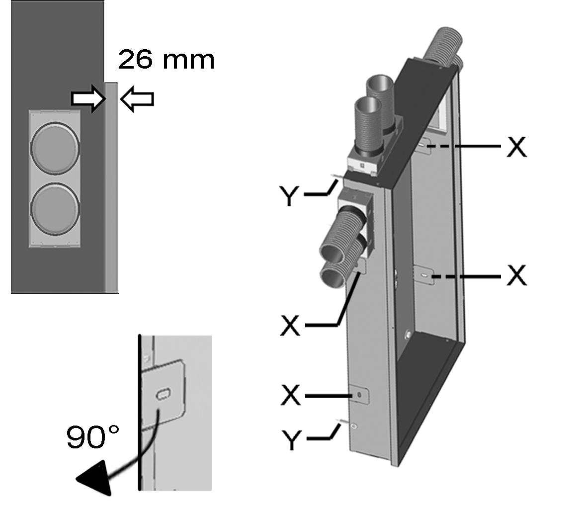
X
Fastening tab (4x)
Y
Fixing screw (4x)

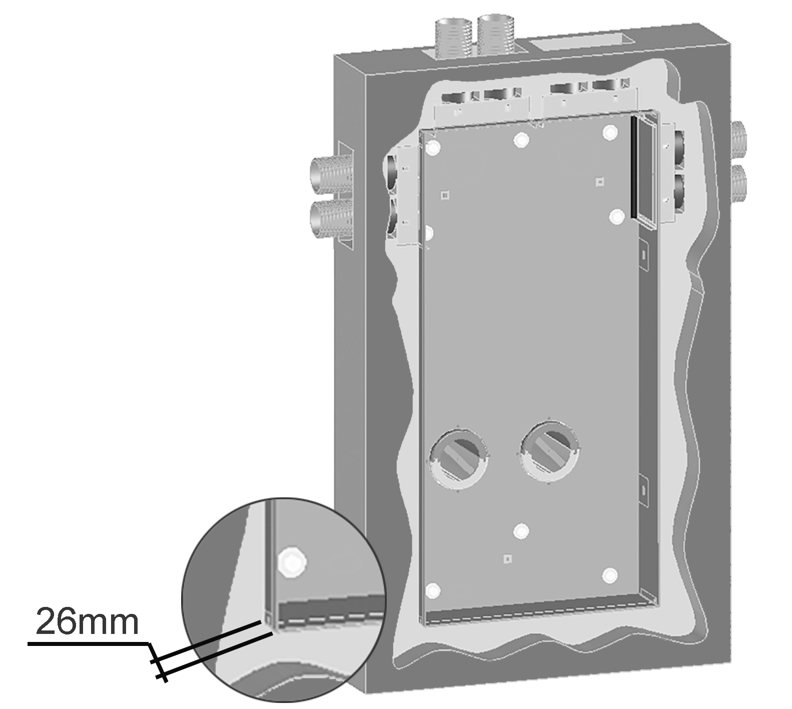
- Insert shell tray into wall and secure. Allow a distance of 26 mm to the finished tiled/plastered wall. Screw down tray at the 4 lateral fastening tabs [X]. Alternatively, the shell tray can be screwed down directly to the wall (4x pos [Y]). If desired, the shell tray can be bricked in, plastered in. ATTENTION: Position OSA/OGA ducts (WW 90 wall sleeves) such that the face end of the duct is flush with the two bent sheet metal stops (step 5). If this is not done, the connection sockets do not sit right when Powerbox is installed. Ensure a slope of 1 to 2 % to the exterior wall for the WW 90 wall sleeves.

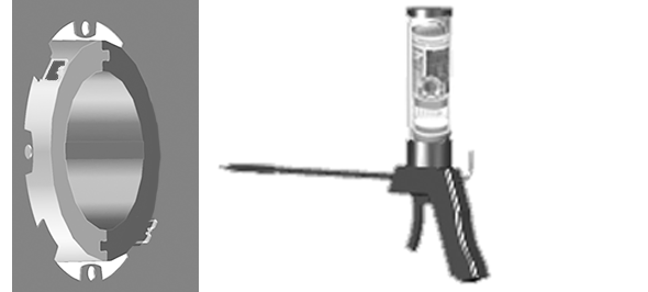
- Use customer-provided mounting foam (non-pressing) to glue the WW 90 wall sleeves into the masonry, sealed all the way round. Only apply the mounting foam tightly on the inside and outside. If walls have a wooden construction, additionally seal the interfaces to this construction. Stick sealing strips to the wall sleeve in these areas. Suitable sealing material is to be provided by the customer.
- During the shell construction phase, protect the WW 90 wall sleeves from soiling with the protective covers provided.
- Install Powerbox H and UPA/UPGA flush-mounted cover and put the ventilation unit into operation → Videos, tutorials and WS 75 final installation instructions.