Retrofitting bypass shutter
- Switch the mains fuse off.
- Tilt front panel forwards at the two top corners (detach from the magnets) and remove upwards.
- Loosen the 4 screws of the inner cover (bayonet lock) and remove it. Note information on sticker.
- Remove the EPP bypass cover from the EPP housing at the rear left of the exhaust duct (position I, small recessed grip at the rear).
- Cut a groove for the connection cable into the EPP housing at position II.
- Push the bypass shutter into the bypass shaft as far as it will go.
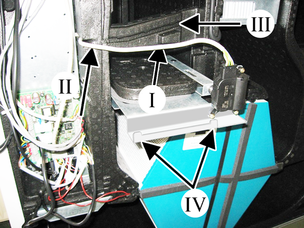
Fig. WS-BP, left-hand version
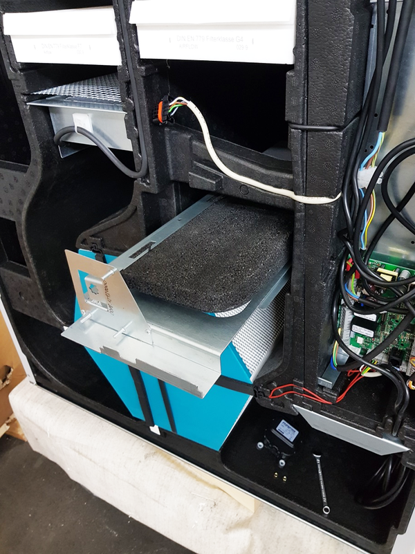
Fig. WS-BP, right-hand version
- Insert the connection cable into the groove, position II and III, so that it is firmly seated.
- Only for right-hand versions: Lift the bypass shutter until the motor can be easily fitted in alignment with its toothing.
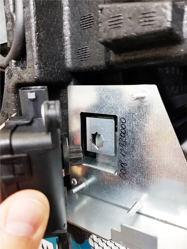
Fig. WS-BP, right-hand version
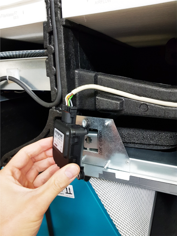
Fig. WS-BP, right-hand version

Fig. WS-BP, right-hand version
- Only for right-hand versions: Screw down bypass motor with 2 nuts.
 One screw remains free because it is not accessible.
- Lift the electronics slide-in module slightly, pull it out of the electronics compartment and hook it into the fitting studs position IV.

- Wire connection cable for bypass motor W7 on the main board (terminal X7) according to wiring diagram.
- Insert the electronics slide-in module into the electronics compartment.
- Insert inner cover into the bottom housing rail, close it and secure it with 4 screws (bayonet lock).
- Fit front panel in the two lugs and close (2 magnets).
- Affix the provided retrofit sticker on the ventilation unit so that it is clearly visible. Enter installed function and date on WS-BP.
- Switch the mains fuse on. Set the main switch to position I/On. On the RLS 1 WR control unit, the LEDs switch on; the start screen appears on an optional RLS T2 WS control unit.
- Connect the PC/notebook to the ventilation unit (USB) → Overview of ventilation unit.
- Call up commissioning software. Select USB connection. The start screen appears.
- Call up the Installer parameter and enter the service code. The programme changes to the Installer level.
- Select the parameter Basic settings/Bypass and activate the bypass with yes. This setting can also be made with the
 -web tool or on the RLS T2 WS control unit.
 - Briefly switch off the ventilation unit with the main switch and switch it on again. The ventilation unit now performs a reference run and closes the bypass (vertical position).
The bypass is automatically blocked if the winter season is selected or at an air inlet temperature < 5 °C.
For more information, see the operating instructions of the ventilation unit.