PP 45 O, PP 45 K
 Wall sleeves, external covers or soffit elements are already installed in accordance with shell installation instructions.
Perform following steps for all ventilation units
- Take inner plaster protective cover out of wall sleeve.
- Check angle of inclination of fitted wall sleeve. There must be an inclination of 1 to 2 % to the exterior wall.
- Route control cables of ventilation units, sensors and accessories in the empty ducts.
- Take off front cover of internal cover’s housing. To do this, press on locking lever on underside of housing and take off cover.
- With PP 45 O and PP 45 K units, route the room air control’s 12 V control cable from the rear side into the internal cover’s internal housing.
- With PP 45 RC units, route the 230 V power cable from the rear side into the internal cover’s internal housing.
- Align the internal cover’s housing horizontally, centred on the wall sleeve and mark the 4 fastening holes.
- Place the dowels and screw the housing to the interior wall with 4 screws. Suitable mounting material is to be provided by the customer. For drilling distances of internal cover Installation dimensions, drilling distances.
Fan unit, ceramic heat exchanger and filter seats, with the two air filters, are already inserted in the slide-in module in the factory. G2 filter facing interior wall, G3 filter facing exterior wall. For filter types → Operating instructions
- Ensure that the air filters lie flat in the holders.
- Slide slide-in module into wall sleeve.
 Risk of injury/damage to unit from falling slide-in module (3 kg). Sometimes the slide-in module is hard to slide in. Ensure that you are standing securely and cannot lose your balance and that there is no one under the unit.
When installing and removing the slide-in module, support it from below with a hand.
Minimum wall thickness 265 mm, slide-in module must not protrude out of wall sleeve. The profile seal on the outside of the slide-in module serves to fix the unit in place and avoid air from infiltrating. The motor connection cable must not be strained when installed. When sliding in the slide-in module, ensure that the `Oben/Top´ sticker is facing upwards.

- Press fan connection cable into notch (arrow) so that it is fixed and not strained.
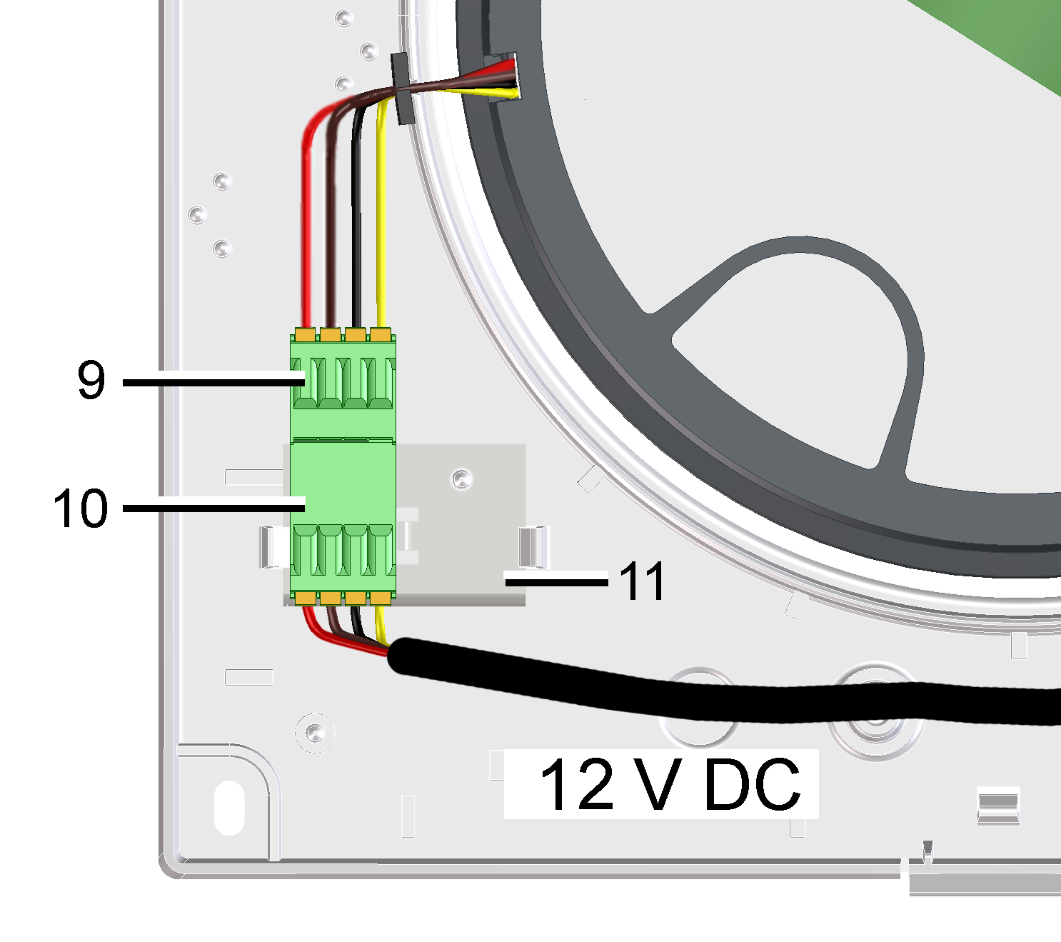
9 | Fan connection cable |
10 | Plug |
11 | Enclosed sheet metal |
- With PP 45 O units (12 V DC), insert the enclosed sheet metal in the 2 locking tabs so that it engages. Wire connector with the 12 V control cable of the room air control (Connection and wiring diagrams in appendix). Plug connector onto the sheet metal and connect it with plug.

- For PP 45 K units (12 V DC) loosen the screws of the circuit board cover, remove the cover. Plug the fan connection cable directly onto the circuit board. Wire the 12 V control cable of the room air control (Connection and wiring diagrams in appendix). Fit circuit board cover.
- Attach front cover of internal housing at top in two housing studs and swivel down until front cover engages on locking lever.