Installing the PPB 30 O/K/RC slide-in module with extension duct

- Produce fixing holes for the internal cover. Use enclosed drilling template. Note the TOP unit position. Insert dowel.
- Slide extension duct into wall sleeve, with centring ring(s), up to stop of the external cover. Ensure that the centring ring is positioned as far inside as possible. If needed, fix centring ring on wall sleeve with adhesive tape.
- With PPB 30 VS extension, use two centring rings. The sealing strip must fit tightly in the external cover.
- Remove electronics compartment cover (2 screws).
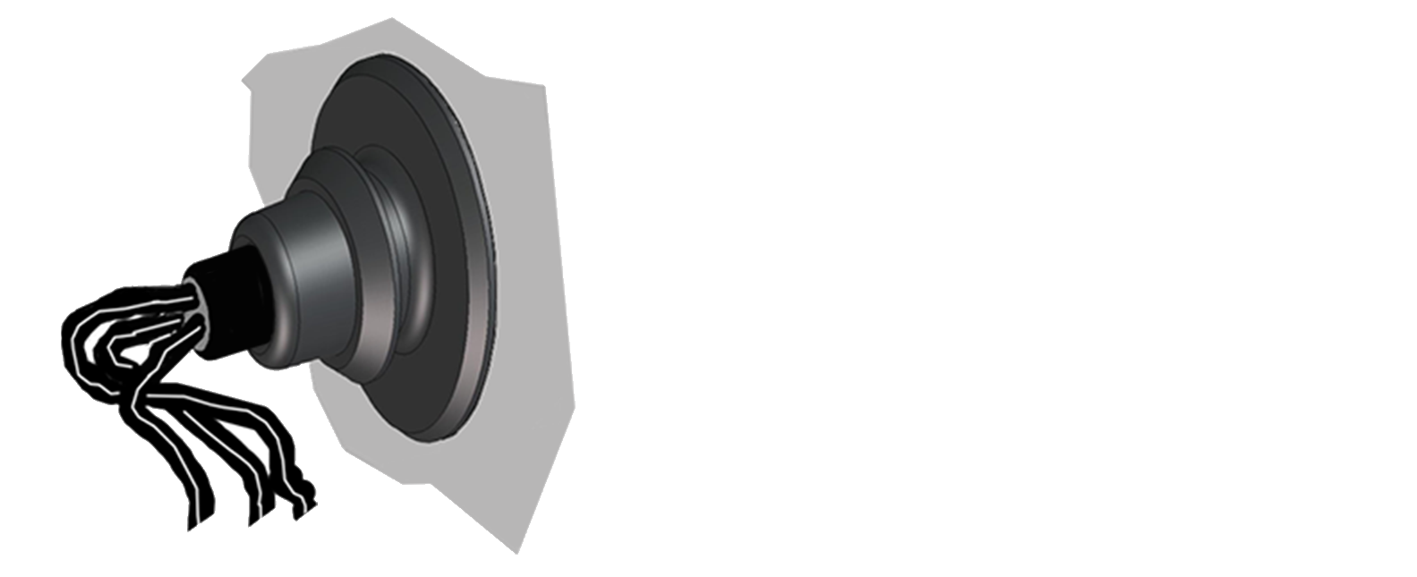
- Use thin screwdriver to pierce cable grommet in internal housing.
 Damage to unit from water ingress if the connecting cable is incorrectly fed into the internal housing or if the cable grommet is not fitted correctly.
Pierce cap of cable grommet so that it can tightly seal the power cable. The cable grommet must be correctly attached in the housing.
- If using PPB 30 K units and connection of an optional button or switch, the second input is used with the relevant grommet → Figure.
- Slide complete slide-in unit a little into the wall sleeve with the internal cover. Guide connecting cable(s) through cable grommet(s) into terminal compartment.
- Slide complete slide-in unit into the wall sleeve with the internal cover until stop is reached. The sealing strip must fit tightly in the extension duct.
- Screw internal cover down to wall with 4 screws. Note the TOP unit position. Suitable mounting material is to be provided by the customer.
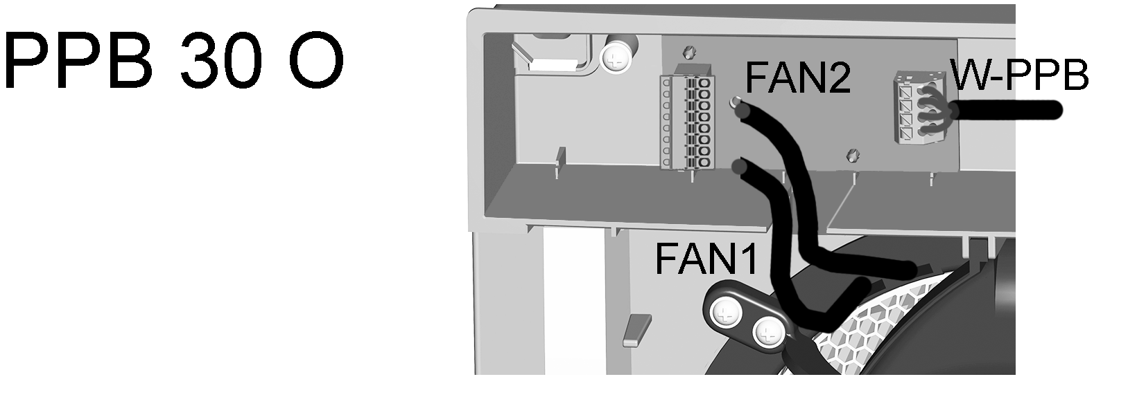
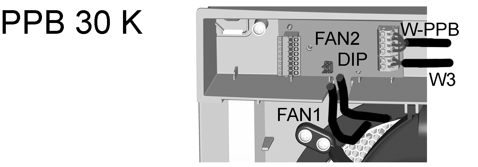
- Make the unit connection according to the connection diagram in the appendix → Observe the unit variant.
- PPB 30 K / PPB 30 RC: If desired, connect a button to start the exhaust air mode or intensive ventilation function → Wiring diagrams in appendix.
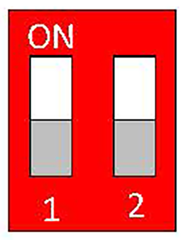
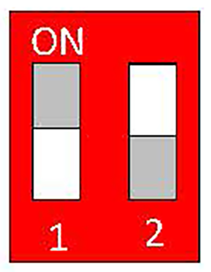
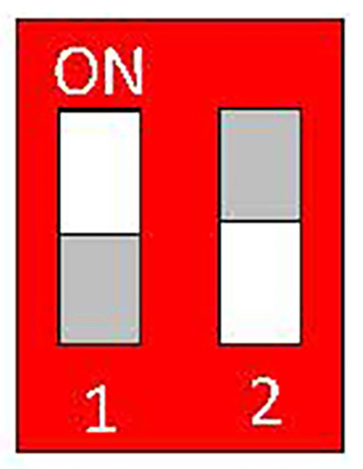
- When connecting multiple PPB 30 K: Address the units at the DIP switch → Connection diagrams in the appendix.
| PPB 30 K unit #1 |
| PPB 30 K units #2 |
| PPB 30 K units #3 |
- Fit electronics compartment cover and screw down (2 screws).
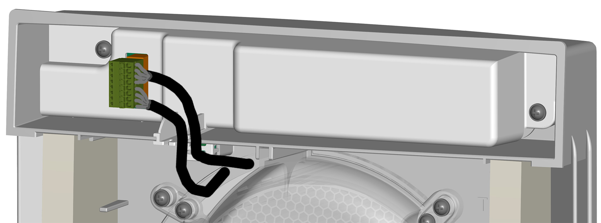
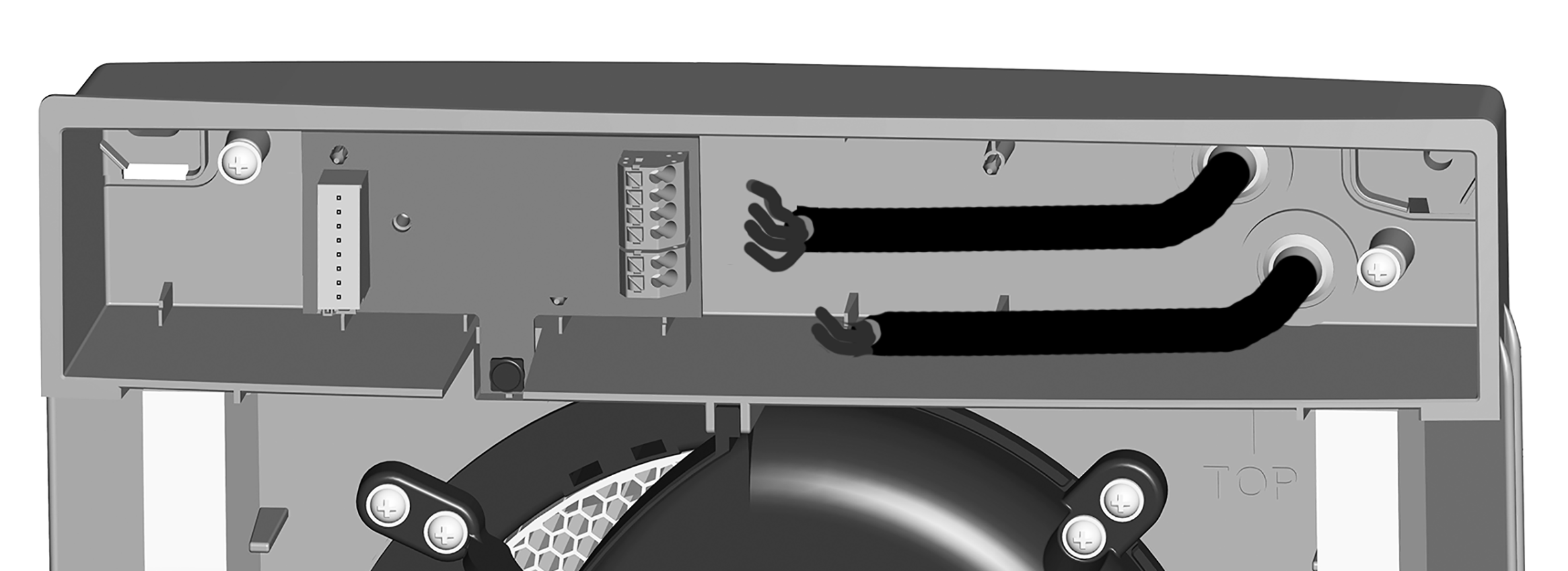
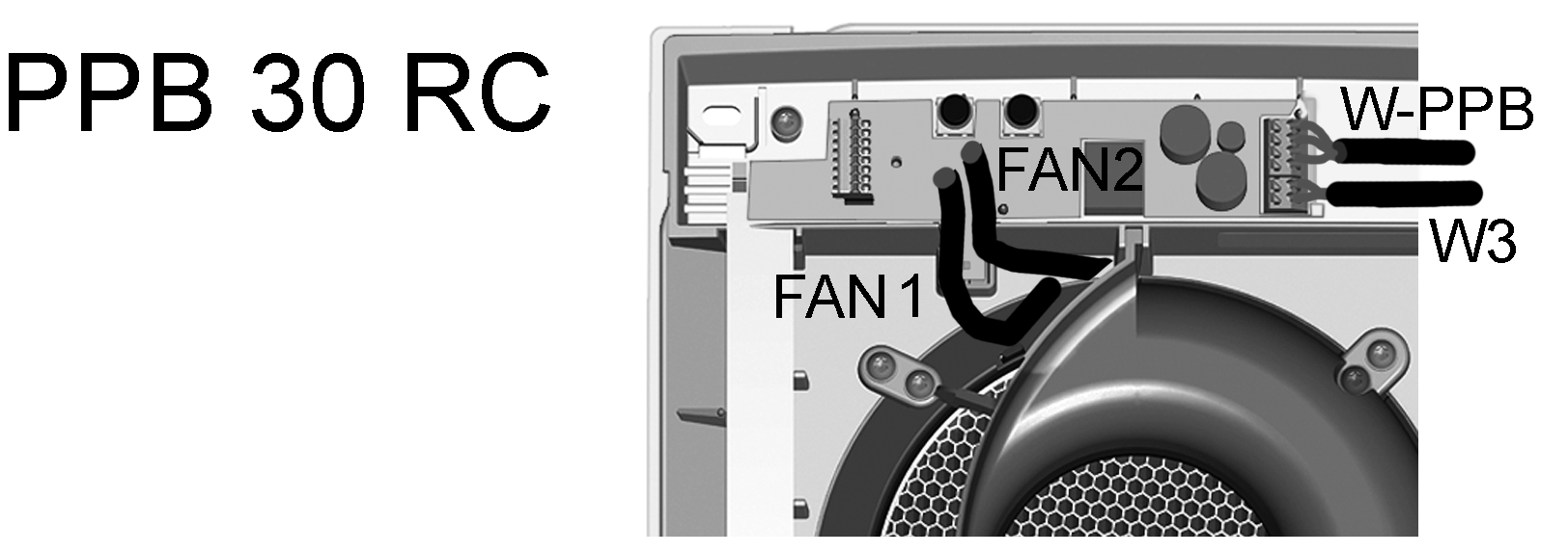
- Plug in plugs (8-pin) of both fan connecting cables directly onto the circuit board. The plugs are coded and cannot be confused. Insert connecting cables in intended slot in the housing. With PPB 30 K/ PPB 30 RC units, ensure that the humidity sensor is not covered.
- Ensure that the two G3 air filters are correctly inserted in the holders.
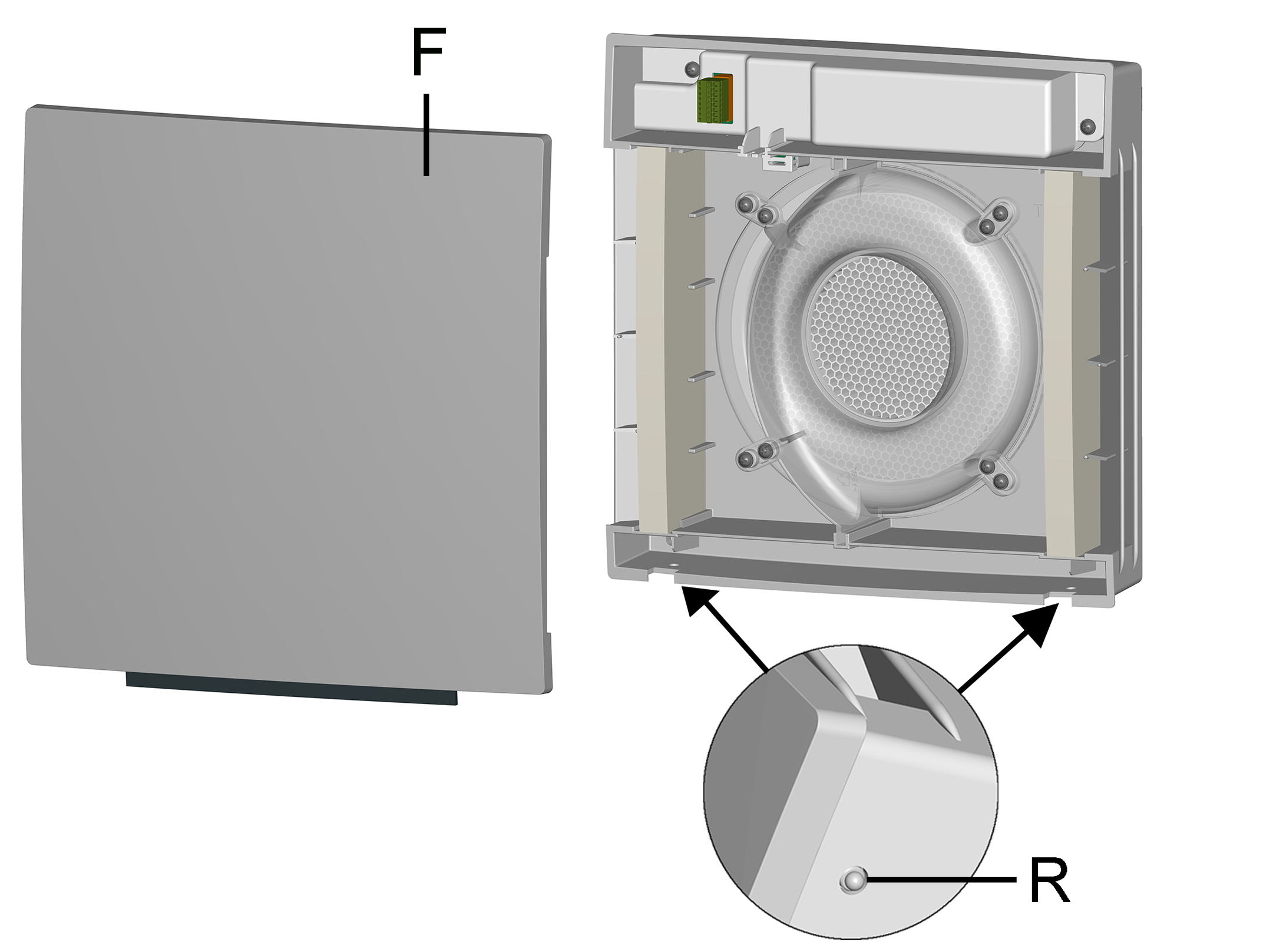
F
Front cover
R
Locking lever
- Attach front cover and swivel down until the front cover engages at the two locking levers.