Electrical connection
 Damage to the unit due to a short circuit if water enters the electronics compartment.
- Ensure correct, tight line feedthrough through the cable feedthrough and membrane grommet with slot.
Danger of injury due to sharp edges on sheet metal/break-outs in the housing or in the electronics compartment.
Wear protective gloves if necessary. Carefully guide connecting cables into unit. Do not damage cables.
 If the connecting cables are too short, the electronics unit cannot be fully pulled out and fitted on the housing. Ensure connection cables of a sufficient length inside the ventilation unit.
A fixed wiring for the mains connection is mandatory. The power cable is already wired inside the unit and led out of the unit.
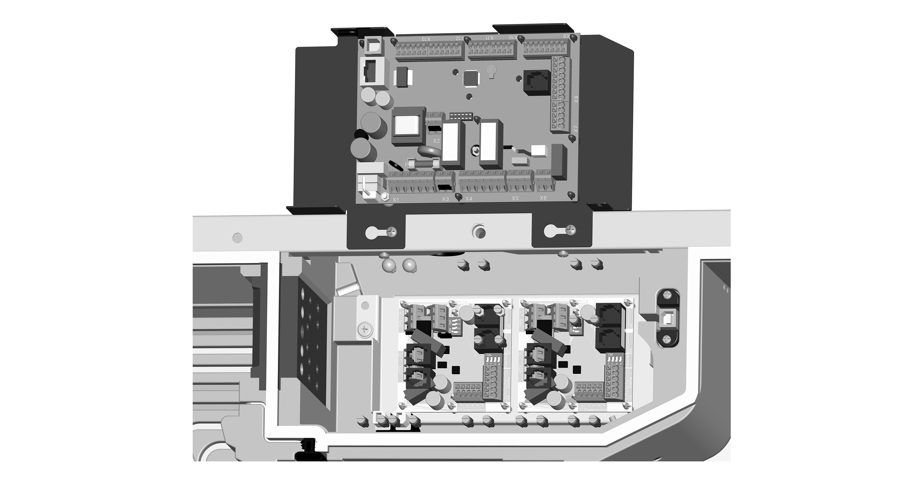
Take electronics unit (with A1 main board) out of ventilation unit and attach as described below.
- Switch the mains fuse off.
- Remove the front cover → Installation of WS 160 Flat or Installation of WS 300 Flat.
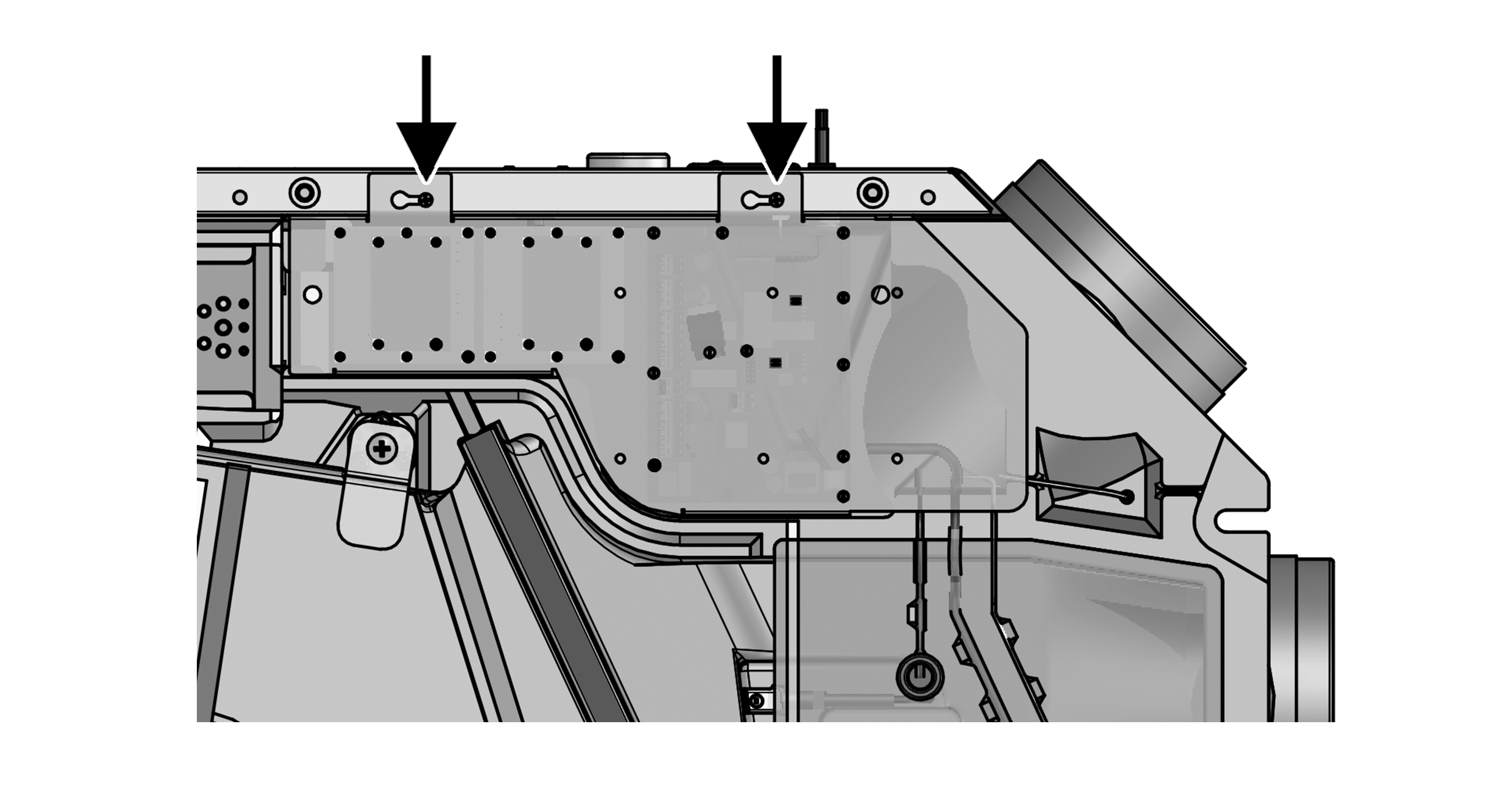
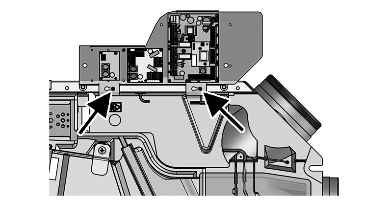
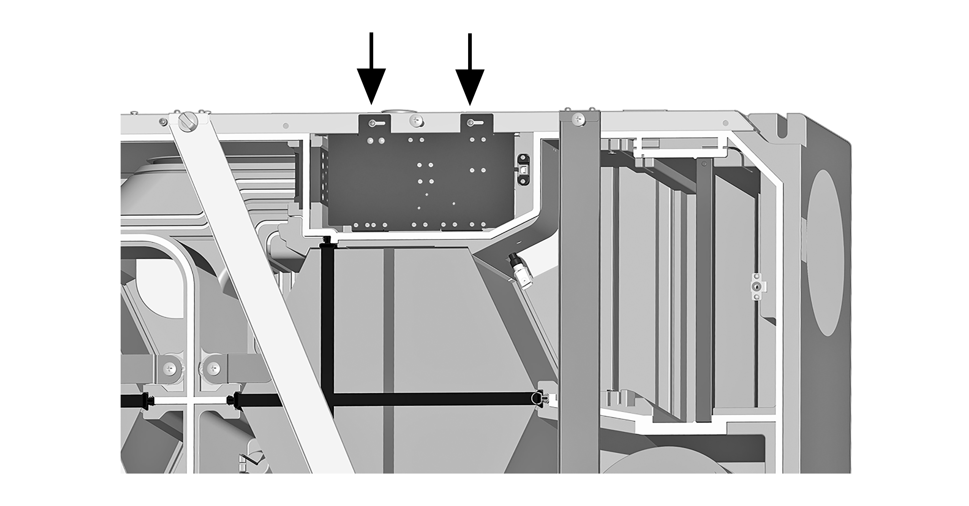
Arrow | Fitting studs |
Figures: WS 160 Flat ventilation unit
Figures: WS 300 Flat ventilation unit
- Slightly loosen the two screws on the electronics unit.
- Take the electronics unit out of the ventilation unit and attach to studs.
- Install optional additional circuit board(s) ZP 1 and/or ZP 2 in the slots and connect with the provided connection cables. Check DIP switch settings and adjust if necessary. For electrical connection and DIP switch settings mounting instructions for respective accessories.
- Plug optional KNX plug-in module (K-SM) or EnOcean plug-in module (E-SM) into slot X01 of the main board →installation instructions of the accessories.
- Guide connecting cable of operating units and additional components through cable feedthrough(s) into ventilation unit. Ensure seal integrity (IP protection).
- Produce electrical connection: Wire up electrics of connection cables according to wiring diagram → Circuit diagrams, wiring diagrams.
- For connection variants of the additional components → installation instructions of the accessories.
- Install control unit(s) → and installation instructions of the accessories.
- Insert and screw down electronics unit.
- Attach front cover(s) → Installation of WS 160 Flat or Installation of WS 300 Flat.
- Run function test: Switch the mains fuse on. The LEDs on the RLS 1 WR switch on.
- Download commissioning software. For system requirements and download → Commissioning.
- Set up and regulate ventilation unit.