Surface mounting of WS 75 RSAP: Outgoing air/outside air connections on the wall side, supply air/exhaust air on side via WS 75 APA cover
The outgoing air/outside air ducts are guided through the exterior wall on the rear wall side of the RSAP.
In the Powerbox H unit, the supply air and exhaust air are directed laterally through supply air and exhaust air openings through the APA surface-mounted cover. For additional supply air/exhaust air connections on the rear wall → Following chapter.
- Preparing the installation site → Installation conditions, installation preparations.
- Align the RSUP shell tray (vertically or horizontally depending on the installation position) and mark the two centres of the core drill holes.
- Drill both core holes into the wall with a Ø of at least 160 mm.

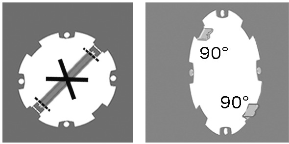
- Break out the sheet metal cross struts on both cut-outs (OGA/OSA).
- Angle the two stops 90° towards the interior room on the two cut-outs.
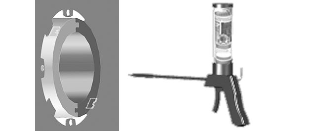
- Loosely insert the supplied WW 90 thermally insulated wall sleeves (thermally insulated ducts) for outside air and outgoing air (OSA/OGA) into the two core drill holes. Allow for interior/exterior wall side and installation position with slot facing vertically down.
ATTENTION: The WW 90 must be pushed in so far that they are flush with the tabs of the stop plate.
ATTENTION: On the exterior wall side, the ducts are cut to length when mounting the external cover. The WW 90 ducts must protrude 10 to 20 mm beyond the exterior wall. The projection is needed as a drip edge. Damage to the exterior wall if installed incorrectly.

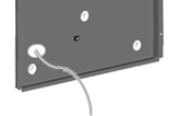
- Use a hammer to press out/detach one of the pre-punched cable feedthroughs from the RSAP metal shell sheet.
- Insert the power cable through the cable feedthrough from the rear side of the RSAP. If the control unit is placed externally (outside the WS 75 APA cover), also guide the control cable through cable feedthrough. ATTENTION: Do not damage cables on sharp sheet metal edges.

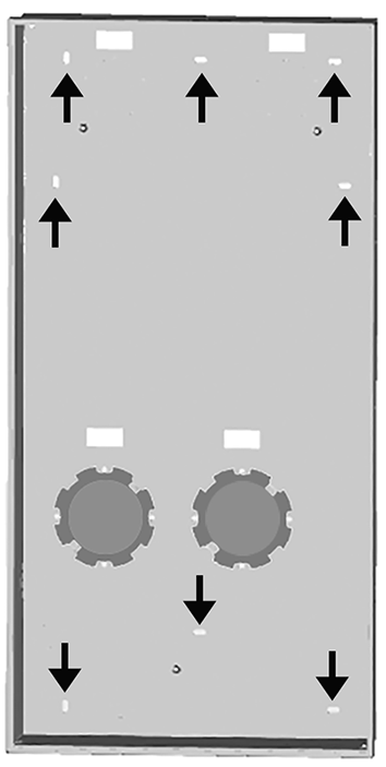
- Screw the RSAP metal shell sheet to the finished tiled/plastered wall with 4 screws. Choose screw positions from the 8 pre-punched mounting holes. ATTENTION: Position OSA/OGA ducts (WW 90 thermally insulated wall sleeves) such that the face end of the duct is flush with the two bent stops (step 5). If this is not done, the connection sockets will not be seated correctly when the Powerbox H is installed. Ensure a slope of 1 to 2 % to the exterior wall for the WW 90 ducts.

- Use customer-provided mounting foam (non-pressing) to glue the WW 90 wall sleeves into the masonry, sealed all the way round. Only apply the mounting foam tightly on the inside and outside. If walls have a wooden construction, additionally seal the interfaces to this construction. Stick sealing strips to the wall sleeve in these areas. Suitable sealing material is to be provided by the customer.
- During the shell construction phase, protect the WW 90 wall sleeves from soiling with the protective covers provided.
- Mount Powerbox H and APA surface-mounted cover and put ventilation unit into operation → Videos, tutorials and WS 75 final installation instructions.
 With standard installation of the control unit in the WS 75 APA cover, the enclosed connection cable is routed from the front into the electronics compartment of the ventilation unit. Do not lead the connection cable through the RSAP metal shell sheet