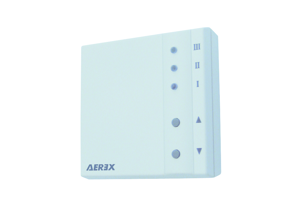
RLS 1 WR: Control elements, LEDs

The ventilation levels can be set manually with the RLS 1 WR control panel. LEDs indicate the selected ventilation level, a pending filter change or faults.
Ventilation level I | Ventilation for humidity protection (building preservation). LED I flashes. Interval ventilation 13 minutes on – 17 minutes off – 13 minutes on. |
Ventilation level I | Reduced ventilation. LED I on. Continuous operation. |
Ventilation level II | Nominal ventilation. LED II on. Continuous operation. Ventilation unit in Auto sensor operating mode. |
Ventilation level III | Intermittent ventilation. LED III flashes. Intensive ventilation with timer. Once a timer interval has elapsed, the ventilation unit switches back to nominal ventilation |
Ventilation level III | Intensive ventilation. LED III on. Continuous operation. |
Filter change indicator | LED II flashes. |
Fault display | All 3 LEDs flash on the RLS 1 WR. The fault elimination must be acknowledged manually. Press both arrow keys at the same time for 3 seconds. |
Operating modes with RLS 1 WR as solo control panel
Manual, Auto sensor or Off
Auto sensor function only active
- with nominal ventilation (ventilation level II),
- if external sensors are connected or
Off function can be deactivated with Single control unit Blocking off parameter (single control unit = RLS 1 WR control panel).
Operating modes when using several RLS 1 WR/EnOcean buttons or in combinations with a touchscreen control unit
Manual, Auto time, Auto sensor, ECO mode supply air, ECO mode exhaust air or Off
- The operating mode is preset via the touchscreen control unit, APP or the web tool.
- Ventilation level adjustment is possible for a limited period of time.
- Off function can be deactivated with Single control unit Blocking off parameter (single control unit = RLS 1 WR control panel).
 Ventilation levels I-III: Shift up with the ▼ button, shift down with the ▲ button.