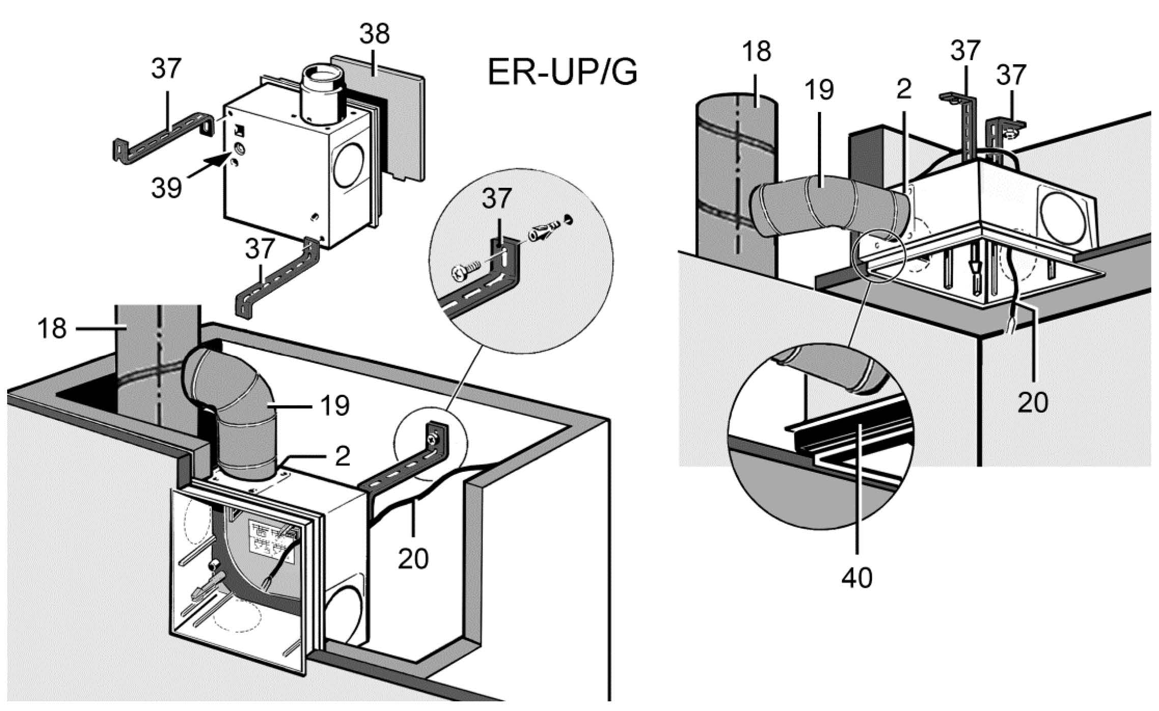
ER-UP/G wall installation, single room

2 | Exhaust socket with plastic shutter |
18 | Main duct, steel folded spiral-seams duct |
19 | Connection duct, AFR 80 DN 75/80 flexible aluminium duct |
20 | Power cable |
37 | Mounting support UPM 60/100 or ER-UPM (2 items) |
38 | Plaster protective cover |
39 | Cable grommet |
40 | ER-MO expanded rubber |
- Remove the plaster protective cover from the housing.
 The unit will be damaged and function impaired if the fixing screws used are incorrect/too long.
Fixing screws may not penetrate into the housing.
- Use the screws provided (UPM 60/100 mounting support).
- Cut the mounting support to the required length, bend it into shape and fix it to the housing with the supplied fixing screws.
- Mark fixing holes for mounting support on rear shaft wall, produce holes and insert dowels. Suitable mounting material is to be provided by the customer.
 Danger of short-circuits and damage to the unit.
If the cable grommet is not installed correctly, water may penetrate the housing. The degree of protection can no longer be guaranteed.
- Drive through cable grommet so that it can seal the cable sheathing all the way round (circular, no slots).
- Guide power cable from rear of housing through cable grommet into housing.
- Insert the housing with the mounting support into the shaft and fix it to the rear wall of the shaft.
 Fire may spread if connection duct is incorrectly installed.
- Only use permitted duct material (Requirements in line with approval).
- Correctly attach connection duct to exhaust socket.
- Connect connection duct to exhaust socket sealed for ventilation, e.g. with cold-shrink tape.
- Provide unit with electrical connection: Electrically connecting the unit.
- Insert the plaster protective cover in the housing.
- Plaster in housing flush with front edge, note tile thickness if necessary: Important information about plastering.