Possible combinations
The electrical cable and ventilation connection are to be laid in the shell construction phase.
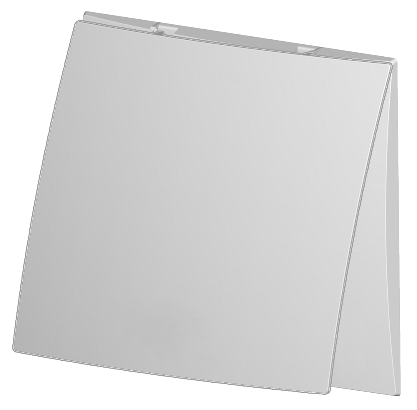
Final installation is undertaken once the plastering and paint work is complete: Place the fan insert into the housing and attach the cover with air filter. For covers ER-AK, ER-AH, ER-AB , adjust the setting values as necessary.
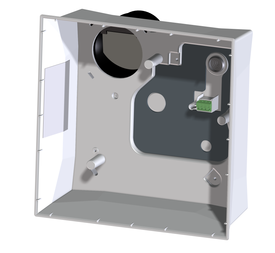
Surface-mounted housing
- DN 75 or DN 80 connection diameter.
- Plastic housing without fire protection equipment. Can be combined with ceiling barrier system.
- Sealed housing with water jet protection for areas 1 (IP X5).
- Turn air outlet to the rear, upwards or to the right side by turning the housing by 90°.
- ER GH AP: Model without fire protection. With maintenance-free plastic backflow preventer.
- ER-APB: Fire protection model with maintenance-free fire protection shut-off device K 90-18017 (metal backflow preventer with soldered strut).
- Exhaust socket locked in housing.
- Electrical connection at rear. Cable feedthrough with stepped grommet.
- Mains cable type NYM-O or NYM-J, 3 x 1.5 or 5 x 1.5 mm²
- For the wall or ceiling installation, outside the exhaust air shaft.
- Permissible air outlet direction for wall installation towards the rear.
- Fan insert is fastened with 3 screws.
Fan insert
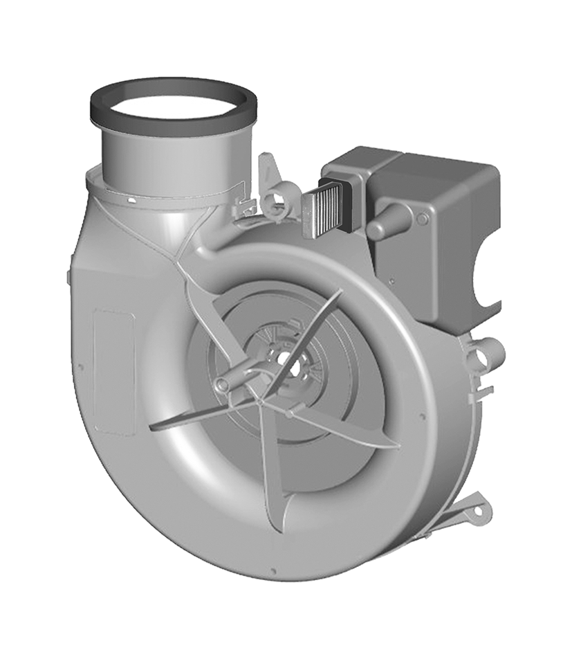
- Fan insert for installation in housing.
- Electrical plug connection for quick installation in the housing.
- Energy-saving EC motor.
- Motor not speed controllable.
- Air outlet adapter (scope of delivery) for conversion of air outlet towards the rear (Conversion of air outlet adapter for using the housing).
Covers
- Cover with exhaust air filter. Trouble-free filter change without tools.
- ER-AH and ER-AB: Barrier-free products, switch on and off automatically.
- ER EC/ER EC 2.1 fans with water jet protection for areas 1 (DIN VDE 0100-701).


